
Data Sheet

433
Atmel | SMART SAM D21 [DATASHEET]
Atmel-42181G–SAM-D21_Datasheet–09/2015
24.5 Product Dependencies
In order to use this peripheral, other parts of the system must be configured correctly, as described below.
24.5.1 I/O Lines
Using the SERCOM I/O lines requires the I/O pins to be configured using port configuration (PORT). Refer to “PORT” on
page 379 for details.
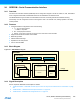
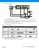
From Figure 24-1 one can see that the SERCOM has four internal pads, PAD[3:0]. The signals from I
2
C, SPI and USART
are routed through these SERCOM pads via a multiplexer. The configuration of the multiplexer is available from the
different SERCOM modes. Refer to the mode specific chapters for details:
z “SERCOM USART – SERCOM Universal Synchronous and Asynchronous Receiver and Transmitter” on page
440
z “SERCOM SPI – SERCOM Serial Peripheral Interface” on page 478
z “SERCOM I2C – SERCOM Inter-Integrated Circuit” on page 511
24.5.2 Power Management
The SERCOM can operate in any sleep mode.SERCOM interrupts can be used to wake up the device from sleep
modes. Refer to “PM – Power Manager” on page 117 for details on the different sleep modes.
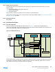
24.5.3 Clocks
The SERCOM bus clock (CLK_SERCOMx_APB) is enabled by default, and can be enabled and disabled in the Power
Manager. Refer to “PM – Power Manager” on page 117 for details.
Two generic clocks are used by the SERCOM: GCLK_SERCOMx_CORE and GCLK_SERCOMx_SLOW. The core clock
(GCLK_SERCOMx_CORE) is required to clock the SERCOM while operating as a master, while the slow clock
(GCLK_SERCOMx_SLOW) is only required for certain functions. See specific mode chapters for details.
These clocks must be configured and enabled in the Generic Clock Controller (GCLK) before using the SERCOM. Refer
to “GCLK – Generic Clock Controller” on page 95 for details.
These generic clocks are asynchronous to the user interface clock (CLK_SERCOMx_APB). Due to this asynchronicity,
writes to certain registers will require synchronization between the clock domains. Refer to “Synchronization” on page
439 for further details.
24.5.4 DMA
The DMA request lines are connected to the DMA controller (DMAC). Using the SERCOM DMA requests, requires the
DMA controller to be configured first. Refer to “DMAC – Direct Memory Access Controller” on page 272 for details.
24.5.5 Interrupts
The interrupt request line is connected to the Interrupt Controller. Using the SERCOM interrupts requires the Interrupt
Controller to be configured first. Refer to “Nested Vector Interrupt Controller” on page 34 for details.
24.5.6 Events
Not applicable.
24.5.7 Debug Operation
When the CPU is halted in debug mode, the SERCOM continues normal operation. If the SERCOM is configured in a
way that requires it to be periodically serviced by the CPU through interrupts or similar, improper operation or data loss
may result during debugging. The SERCOM can be forced to halt operation during debugging.