
Data Sheet

36
Atmel | SMART SAM D21 [DATASHEET]
Atmel-42181G–SAM-D21_Datasheet–09/2015
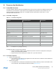
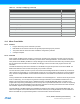
10.3 Micro Trace Buffer
10.3.1 Features
z Program flow tracing for the Cortex-M0+ processor
z MTB SRAM can be used for both trace and general purpose storage by the processor
z The position and size of the trace buffer in SRAM is configurable by software
z CoreSight compliant
10.3.2 Overview
When enabled, the MTB records changes in program flow, reported by the Cortex-M0+ processor over the execution
trace interface shared between the Cortex-M0+ processor and the CoreSight MTB-M0+. This information is stored as
trace packets in the SRAM by the MTB. An off-chip debugger can extract the trace information using the Debug Access
Port to read the trace information from the SRAM. The debugger can then reconstruct the program flow from this
information.
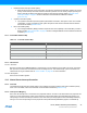
The MTB simultaneously stores trace information into the SRAM, and gives the processor access to the SRAM. The
MTB ensures that trace write accesses have priority over processor accesses.
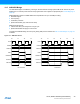
The execution trace packet consists of a pair of 32-bit words that the MTB generates when it detects the processor PC
value changes non-sequentially. A non-sequential PC change can occur during branch instructions or during exception
entry. See the CoreSight MTB-M0+ Technical Reference Manual for more details on the MTB execution trace packet
format.
Tracing is enabled when the MASTER.EN bit in the Master Trace Control Register is 1. There are various ways to set the
bit to 1 to start tracing, or to 0 to stop tracing. See the CoreSight Cortex-M0+ Technical Reference Manual for more
details on the Trace start and stop and for a detailed description of the MTB’s MASTER register. The MTB can be
programmed to stop tracing automatically when the memory fills to a specified watermark level or to start or stop tracing
by writing directly to the MASTER.EN bit. If the watermark mechanism is not being used and the trace buffer overflows,
then the buffer wraps around overwriting previous trace packets.
The base address of the MTB registers is 0x41006000; this address is also written in the CoreSight ROM Table. The
offset of each register from the base address is fixed and as defined by the CoreSight MTB-M0+ Technical Reference
Manual. The MTB has 4 programmable registers to control the behavior of the trace features:
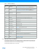
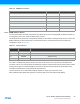
TC3 – Timer Counter 3 18
TC4 – Timer Counter 4 19
TC5 – Timer Counter 5 20
TC6 – Timer Counter 6 21
TC7 – Timer Counter 7 22
ADC – Analog-to-Digital Converter 23
AC – Analog Comparator 24
DAC – Digital-to-Analog Converter 25
PTC – Peripheral Touch Controller 26
I2S - Inter IC Sound 27
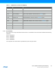
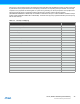
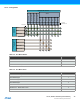
Table 10-3. Interrupt Line Mapping (Continued)
Peripheral Source NVIC Line