
Data Sheet


357
Atmel | SMART SAM D21 [DATASHEET]
Atmel-42181G–SAM-D21_Datasheet–09/2015
21.6.2 Basic Operations
21.6.2.1 Initialization
After power up, the NVM Controller goes through a power-up sequence. During this time, access to the NVM Controller
from the AHB bus is halted. Upon power-up completion, the NVM Controller is operational without any need for user
configuration.
21.6.2.2 Enabling, Disabling and Resetting
Not applicable.
21.6.3 Memory Organization
Refer to “Physical Memory Map” on page 29 for memory sizes and addresses for each device.
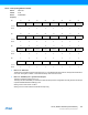
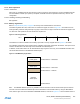
The NVM is organized into rows, where each row contains four pages, as shown in Figure 21-2. The NVM has a row-
erase granularity, while the write granularity is by page. In other words, a single row erase will erase all four pages in the
row, while four write operations are used to write the complete row.
Figure 21-2. Row Organization
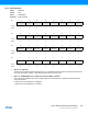
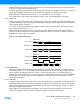
The NVM block contains a calibration and auxiliary space that is memory mapped. Refer to Figure 21-3
for details.
The calibration and auxiliary space contains factory calibration and system configuration information. This space can be
read from the AHB bus in the same way as the main NVM main address space.
In addition, a boot loader section can be allocated at the beginning of the main array, and an EEPROM emulation area
can be allocated at the end of the NVM main address space.
Figure 21-3. NVM Memory Organization
Note: The RWWEE address space is only available in Device Variant B. In Device Variant A this space is reserved.
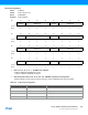
The lower rows in the NVM main address space can be allocated as a boot loader section by using the BOOTPROT
fuses, and the upper rows can be allocated to EEPROM emulation, as shown in Figure 21-4. The boot loader section is
Page (n * 4) + 0Row n Page (n * 4) + 1Page (n * 4) + 2Page (n * 4) + 3
Calibration and
Auxillary Space
RWWEE
Address Space
NVM Main
Address Space
NVM Base Address + 0x00800000
NVM Base Address + 0x00010000
NVM Base Address + NVM Size
NVM Base Address