
Data Sheet

34
Atmel | SMART SAM D21 [DATASHEET]
Atmel-42181G–SAM-D21_Datasheet–09/2015
z Nested Vectored Interrupt Controller (NVIC)
z External interrupt signals connect to the NVIC, and the NVIC prioritizes the interrupts. Software can set the
priority of each interrupt. The NVIC and the Cortex-M0+ processor core are closely coupled, providing low
latency interrupt processing and efficient processing of late arriving interrupts. Refer to “Nested Vector
Interrupt Controller” on page 34 and the Cortex-M0+ Technical Reference Manual for details
(www.arm.com).
z System Control Block (SCB)
z The System Control Block provides system implementation information, and system control. This includes
configuration, control, and reporting of the system exceptions. Refer to the Cortex-M0+ Devices Generic
User Guide for details (www.arm.com).
z Micro Trace Buffer (MTB)
z The CoreSight MTB-M0+ (MTB) provides a simple execution trace capability to the Cortex-M0+ processor.
Refer to section “Micro Trace Buffer” on page 36 and the CoreSight MTB-M0+ Technical Reference Manual
for details (www.arm.com).
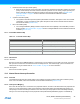
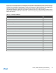
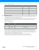
10.1.3 Cortex-M0+ Address Map
Table 10-2. Cortex-M0+ Address Map
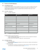
10.1.4 I/O Interface
10.1.4.1 Overview
Because accesses to the AMBA® AHB-Lite™ and the single cycle I/O interface can be made concurrently, the Cortex-
M0+ processor can fetch the next instructions while accessing the I/Os. This enables single cycle I/O accesses to be
sustained for as long as needed. Refer to “CPU Local Bus” on page 381 for more information.
10.1.4.2 Description
Direct access to PORT registers.
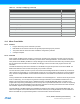
10.2 Nested Vector Interrupt Controller
10.2.1 Overview
The Nested Vectored Interrupt Controller (NVIC) in the SAM D21 supports 32 interrupt lines with four different priority
levels. For more details, refer to the Cortex-M0+ Technical Reference Manual (www.arm.com).
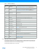
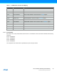
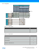
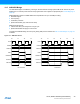
10.2.2 Interrupt Line Mapping
Each of the 28 interrupt lines is connected to one peripheral instance, as shown in the table below. Each peripheral can
have one or more interrupt flags, located in the peripheral’s Interrupt Flag Status and Clear (INTFLAG) register. The
interrupt flag is set when the interrupt condition occurs. Each interrupt in the peripheral can be individually enabled by
writing a one to the corresponding bit in the peripheral’s Interrupt Enable Set (INTENSET) register, and disabled by
Address Peripheral
0xE000E000 System Control Space (SCS)
0xE000E010 System Timer (SysTick)
0xE000E100 Nested Vectored Interrupt Controller (NVIC)
0xE000ED00 System Control Block (SCB)
0x41006000 (see also “Product Mapping” on page 28) Micro Trace Buffer (MTB)