
Data Sheet

277
Atmel | SMART SAM D21 [DATASHEET]
Atmel-42181G–SAM-D21_Datasheet–09/2015
z Destination address for the block transfer must be selected by writing the Block Transfer Destination
Address (DSTADDR) register
If CRC calculation is needed the CRC module must be configured before it is enabled, as outlined by the following steps:
z CRC input source must selected by writing the CRC Input Source bit group in the CRC Control register
(CRCCTRL.CRCSRC)
z Type of CRC calculation must be selected by writing the CRC Polynomial Type bit group in the CRC Control
register (CRCCTRL.CRCPOLY)
z If I/O is chosen as input source, the beat size must be selected by writing the CRC Beat Size bit group in the CRC
Control register (CRCCTRL.CRCBEATSIZE)
19.6.2.2 Enabling, Disabling and Resetting
The DMAC is enabled by writing a one to the DMA Enable bit in the Control register (CTRL.DMAENABLE). The DMAC is
disabled by writing a zero to CTRL.DMAENABLE.
A DMA channel is enabled by writing a one to Enable bit in the Channel Control A register (CHCTRLA.ENABLE), after
writing the corresponding channel id to the Channel ID bit group in the Channel ID register (CHID.ID). A DMA channel is
disabled by writing a zero to CHCTRLA.ENABLE.
The CRC is enabled by writing a one to the CRC Enable bit in the Control register (CTRL.CRCENABLE). The CRC is
disabled by writing a zero to CTRL.CRCENABLE.
The DMAC is reset by writing a one to the Software Reset bit in the Control register (CTRL.SWRST), when the DMAC
and CRC are disabled. All registers in the DMAC, except DBGCTRL, will be reset to their initial state.
A DMA channel is reset by writing a one to the Software Reset bit in the Channel Control A register (CHCTRLA.SWRST),
after writing the corresponding channel id to the Channel ID bit group in the Channel ID register (CHID.ID). The channel
registers will be reset to their initial state. The corresponding DMA channel must be disabled in order for the reset to take
effect.
19.6.2.3 Transfer Descriptors
Together with the channel configurations the transfer descriptors decides how a block transfer should be executed.
Before a DMA channel is enabled (CHCTRLA.ENABLE is written to one), and receives a transfer trigger, its first transfer
descriptor has to be initialized and valid (BTCTRL.VALID). The first transfer descriptor describes the first block transfer of
a transaction. For further details on the content of a transfer descriptor, refer to “Block Transfer Control” on page 329.
All transfer descriptors must reside in SRAM and the addresses stored in the Descriptor Memory Section Base Address
(BASEADDR) and Write-Back Memory Section Base Address (WRBADDR) registers tells the DMAC where to find the
descriptor memory section and the write-back memory section.
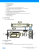
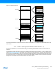
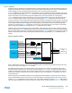
The descriptor memory section is where the DMAC expects to find the first transfer descriptors for all DMA channels. As
BASEADDR points only to the first transfer descriptor of channel 0, refer to Figure 19-3, all first transfer descriptors must
be stored in a contiguous memory section, where the transfer descriptors must be ordered according to their channel
number. Figure 19-3 shows an example of linked descriptors on DMA channel 0. For further details on linked descriptors,
refer to “Linked Descriptors” on page 284.
The write-back memory section is the section where the DMAC stores the transfer descriptors for the ongoing block
transfers. WRBADDR points to the ongoing transfer descriptor of channel 0. All ongoing transfer descriptors will be
stored in a contiguous memory section where the transfer descriptors are ordered according to their channel number.
Figure 19-3 shows an example of linked descriptors on DMA channel 0. For further details on linked descriptors, refer to
“Linked Descriptors” on page 284.