
Data Sheet

234
Atmel | SMART SAM D21 [DATASHEET]
Atmel-42181G–SAM-D21_Datasheet–09/2015
The clock value is continuously compared with the 32-bit Alarm register (ALARM0). When an alarm match occurs, the
Alarm 0 Interrupt flag in the Interrupt Flag Status and Clear registers (INTFLAG.ALARMn0) is set on the next 0-to-1
transition of CLK_RTC_CNT.
A valid alarm match depends on the setting of the Alarm Mask Selection bits in the Alarm 0 Mask register (MASK0.SEL).
These bits determine which time/date fields of the clock and alarm values are valid for comparison and which are
ignored.
If the Clear on Match bit in the Control register (CTRL.MATCHCLR) is one, the counter is cleared on the next counter
cycle when an alarm match with ALARM0 occurs. This allows the RTC to generate periodic interrupts or events with
longer periods than are possible with the prescaler events (see “Periodic Events” on page 234). Note that when
CTRL.MATCHCLR is one, INTFLAG.ALARM0 and INTFLAG.OVF will both be set simultaneously on an alarm match
with ALARM0.
18.6.4 Additional Features
18.6.4.1 Periodic Events
The RTC prescaler can generate events at periodic intervals, allowing flexible system tick creation. Any of the upper
eight bits of the prescaler (bits 2 to 9) can be the source of an event. When one of the Periodic Event Output bits in the
Event Control register (EVCTRL.PEREOn) is one, an event is generated on the 0-to1 transition of the related bit in the
prescaler, resulting in a periodic event frequency of:
f
GCLK_RTC
is the frequency of the internal prescaler clock, GCLK_RTC, and n is the position of the EVCTRL.PEREOn bit.
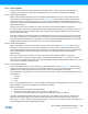
For example, PEREO will generate an event every 8 GCLK_RTC cycles, PEREO1 every 16 cycles, etc. This is shown in
Figure 18-4. Periodic events are independent of the prescaler setting used by the RTC counter, except if
CTRL.PRESCALER is zero. Then, no periodic events will be generated.
Figure 18-4. Example Periodic Events
18.6.4.2 Frequency Correction
The RTC Frequency Correction module employs periodic counter corrections to compensate for a too-slow or too-fast
oscillator. Frequency correction requires that CTRL.PRESCALER is greater than 1.
The digital correction circuit adds or subtracts cycles from the RTC prescaler to adjust the frequency in approximately
1PPM steps. Digital correction is achieved by adding or skipping a single count in the prescaler once every 1024
GCLK_RTC cycles. The Value bit group in the Frequency Correction register (FREQCORR.VALUE) determines the
number of times the adjustment is applied over 976 of these periods. The resulting correction is as follows:
3
_
2
+
=
n
RTCGCLK
PERIODIC
f
f
PEREO0
PEREO1
PEREO2
PEREO3
PEREO4
GCLK_RTC
Correction in PPM
FREQCORR.VALUE
1024 976⋅
-----------------------------------------------------
10
6
PPM⋅=