
Data Sheet


214
Atmel | SMART SAM D21 [DATASHEET]
Atmel-42181G–SAM-D21_Datasheet–09/2015
Enable-protection is denoted by the Enable-Protected property in the register description.
Initialization of the WDT can be done only while the WDT is disabled.
Normal Mode
z Defining the required Time-Out Period bits in the Configuration register (CONFIG.PER).
Normal Mode with Early Warning interrupt
z Defining the required Time-Out Period bits in the Configuration register (CONFIG.PER).
z Defining Early Warning Interrupt Time Offset bits in the Early Warning Interrupt Control register (EWCTRL.
EWOFFSET).
z Setting Early Warning Interrupt Enable bit in the Interrupt Enable Set register (INTENSET.EW).
Window Mode
z Defining Time-Out Period bits in the Configuration register (CONFIG.PER).
z Defining Window Mode Time-Out Period bits in the Configuration register (CONFIG.WINDOW).
z Setting Window Enable bit in the Control register (CTRL.WEN).
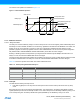
Window Mode with Early Warning interrupt
z Defining Time-Out Period bits in the Configuration register (CONFIG.PER).
z Defining Window Mode Time-Out Period bits in the Configuration register (CONFIG.WINDOW).
z Setting Window Enable bit in the Control register (CTRL.WEN).
z Defining Early Warning Interrupt Time Offset bits in the Early Warning Interrupt Control register (EWCTRL.
EWOFFSET).
z Setting Early Warning Interrupt Enable bit in the Interrupt Enable Set register (INTENSET.EW).
17.6.2.2 Configurable Reset Values
On a power-on reset, some registers will be loaded with initial values from the NVM User Row. Refer to “NVM User Row
Mapping” on page 30 for more details.
This encompasses the following bits and bit groups:
z Enable bit in the Control register (CTRL.ENABLE)
z Always-On bit in the Control register (CTRL.ALWAYSON)
z Watchdog Timer Windows Mode Enable bit in the Control register (CTRL.WEN)
z Watchdog Timer Windows Mode Time-Out Period bits in the Configuration register (CONFIG.WINDOW)
z Time-Out Period in the Configuration register (CONFIG.PER)
z Early Warning Interrupt Time Offset bits in the Early Warning Interrupt Control register (EWCTRL.EWOFFSET)
For more information about fuse locations, see “NVM User Row Mapping” on page 30.
17.6.2.3 Enabling and Disabling
The WDT is enabled by writing a one to the Enable bit in the Control register (CTRL.ENABLE). The WDT is disabled by
writing a zero to CTRL.ENABLE.
The WDT can be disabled only while the Always-On bit in the Control register (CTRL.ALWAYSON) is zero.
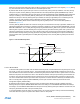
17.6.2.4 Normal Mode
In normal-mode operation, the length of a time-out period is configured in CONFIG.PER. The WDT is enabled by writing
a one to the Enable bit in the Control register (CTRL.ENABLE). Once enabled, if the WDT is not cleared from the
application code before the time-out occurs, the WDT will issue a system reset. There are 12 possible WDT time-out
(TO
WDT
) periods, selectable from 8ms to 16s, and the WDT can be cleared at any time during the time-out period. A new