
Data Sheet

199
Atmel | SMART SAM D21 [DATASHEET]
Atmel-42181G–SAM-D21_Datasheet–09/2015
16.8.14 3.3V Brown-Out Detector (BOD33) Control
Name: BOD33
Offset: 0x34
Reset: 0x00XX00XX
Property: Write-Protected, Write-Synchronized
z Bits 31:22 – Reserved
These bits are unused and reserved for future use. For compatibility with future devices, always write these bits to
zero when this register is written. These bits will always return zero when read.
z Bits 21:16 – LEVEL[5:0]: BOD33 Threshold Level
This field sets the triggering voltage threshold for the BOD33. See the “Electrical Characteristics” on page 935 for
actual voltage levels. Note that any change to the LEVEL field of the BOD33 register should be done when the
BOD33 is disabled in order to avoid spurious resets or interrupts.
These bits are loaded from Flash User Row at startup. Refer to “NVM User Row Mapping” on page 30 for more
details.
z Bits 15:12 – PSEL[3:0]: Prescaler Select
Selects the prescaler divide-by output for the BOD33 sampling mode according to the table below. The input clock
comes from the OSCULP32K 1kHz output.
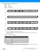
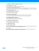
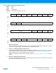
Bit 3130292827262524
AccessRRRRRRRR
Reset00000000
Bit 2322212019181716
LEVEL[5:0]
Access R R R/W R/W R/W R/W R/W R/W
Reset0 0XXXXXX
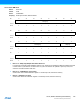
Bit 151413121110 9 8
PSEL[3:0]
CEN MODE
AccessR/WR/WR/WR/W R R R/WR/W
Reset00000000
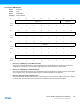
Bit 76543210
RUNSTDBY ACTION[1:0]
HYST ENABLE
Access R R/W R R/W R/W R/W R/W R
Reset000XXXX0