
Data Sheet

151
Atmel | SMART SAM D21 [DATASHEET]
Atmel-42181G–SAM-D21_Datasheet–09/2015
16.5.6 Register Access Protection
All registers with write-access are optionally write-protected by the peripheral access controller (PAC), except the
following registers:
z Interrupt Flag Status and Clear register (INTFLAG - refer to INTFLAG)
Write-protection is denoted by the Write-Protection property in the register description.
When the CPU is halted in debug mode, all write-protection is automatically disabled.
Write-protection does not apply for accesses through an external debugger. Refer to “PAC – Peripheral Access
Controller” on page 41 for details.
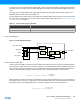
16.5.7 Analog Connections
When used, the 32.768kHz crystal must be connected between the XIN32 and XOUT32 pins, and the 0.4-32MHz crystal
must be connected between the XIN and XOUT pins, along with any required load capacitors. For details on
recommended oscillator characteristics and capacitor load, refer to the “Electrical Characteristics” on page 935 for
details.
16.6 Functional Description
16.6.1 Principle of Operation
XOSC, XOSC32K, OSC32K, OSCULP32K, OSC8M, DFLL48M, FDPLL96M, BOD33, and VREF are configured via
SYSCTRL control registers. Through this interface, the sub-peripherals are enabled, disabled or have their calibration
values updated.
The Power and Clocks Status register gathers different status signals coming from the sub-peripherals controlled by the
SYSCTRL. The status signals can be used to generate system interrupts, and in some cases wake up the system from
standby mode, provided the corresponding interrupt is enabled.
The oscillator must be enabled to run. The oscillator is enabled by writing a one to the ENABLE bit in the respective
oscillator control register, and disabled by writing a zero to the oscillator control register. In idle mode, the default
operation of the oscillator is to run only when requested by a peripheral. In standby mode, the default operation of the
oscillator is to stop. This behavior can be changed by the user, see below for details.
The behavior of the oscillators in the different sleep modes is shown in Table 16-1 on page 151
To force an oscillator to always run in idle mode, and not only when requested by a peripheral, the oscillator
ONDEMAND bit must be written to zero. The default value of this bit is one, and thus the default operation in idle mode is
to run only when requested by a peripheral.
Table 16-1. Behavior of the Oscillators
Oscillator Idle 0, 1, 2 Standby
XOSC Run on request Stop
XOSC32K Run on request Stop
OSC32K Run on request Stop
OSCULP32K Run Run
OSC8M Run on request Stop
DFLL48M Run on request Stop
FDPLL96M Run on request Stop