
Data Sheet


1056
Atmel | SMART SAM D21 [DATASHEET]
Atmel-42181G–SAM-D21_Datasheet–09/2015
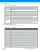
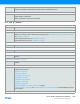
40.1.4 Registers and Bits
Table 40-4. Register and bit mnemonics
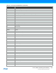
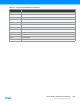
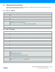
40.2 Acronyms and Abbreviations
Table 40-5 contains acronyms and abbreviations used in this document.
R/W Read/Write accessible register bit. The user can read from and write to this bit.
R Read-only accessible register bit. The user can only read this bit. Writes will be ignored.
W
Write-only accessible register bit. The user can only write this bit. Reading this bit will return an
undefined value.
BIT Bit names are shown in uppercase. (Example PINA1)
BITS[n:m] A set of bits from bit n down to m. (Example: PINA3..0 = {PINA3, PINA2, PINA1, PINA0}
Reserved
Reserved bits are unused and reserved for future use. For compatibility with future devices, always
write reserved bits to zero when the register is written. Reserved bits will always return zero when read.
PERIPHERALi
If several instances of a peripheral exist, the peripheral name is followed by a number to indicate the
number of the instance in the range 0-n. PERIPHERALi denotes one specific instance.
Reset
Value of a register after a power reset. This is also the value of registers in a peripheral after
performing a software reset of the peripheral, except for the Debug Control registers.
SET/CLR
Registers with SET/CLR suffix allows the user to clear and set bits in a register without doing a read-
modify-write operation. These registers always come in pairs. Writing a one to a bit in the CLR register
will clear the corresponding bit in both registers, while writing a one to a bit in the SET register will set
the corresponding bit in both registers. Both registers will return the same value when read. If both
registers are written simultaneously, the write to the CLR register will take precedence.
Table 40-5. Acronyms and Abbreviations
Abbreviation Description
AC Analog Comparator
ADC Analog-to-Digital Converter
ADDR Address
AHB AMBA Advanced High-performance Bus
APB AMBA Advanced Peripheral Bus
AREF Analog reference voltage
AV
DD
Analog supply voltage
BLB Boot Lock Bit
BOD Brown-out detector
CAL Calibration
CC Compare/capture
CLK Clock
CRC Cyclic Redundancy Check
CTRL Control