
Data Sheet

1009
Atmel | SMART SAM D21 [DATASHEET]
Atmel-42181G–SAM-D21_Datasheet–09/2015
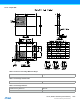
Notes: 1. These values are only given as typical examples.
2. Decoupling capacitor should be placed close to the device for each supply pin pair in the signal group, low
ESR caps should be used for better decoupling.
3. An inductor should be added between the external power and the V
DD
for power filtering.
4. Ferrite bead has better filtering performance than the common inductor at high frequencies. It can be added
between V
DD
and V
DDANA
for preventing digital noise from entering the analog power domain. The bead
should provide enough impedance (e.g. 50Ω at 20MHz and 220Ω at 100MHz) for separating the digital
power from the analog power domain. Make sure to select a ferrite bead designed for filtering applications
with a low DC resistance to avoid a large voltage drop across the ferrite bead.
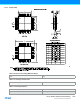
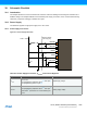
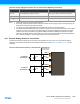
38.3 External Analog Reference Connections
The following schematic checklist is only necessary if the application is using one or more of the external analog
references. If the internal references are used instead, the following circuits in Figure 38-2 and Figure 38-3 are not
necessary.
Figure 38-2. External Analog Reference Schematic With Two References
V
DDCORE
1.6V to 1.8V
Decoupling/filtering capacitor 100nF
(1)(2)
Core supply voltage / external decoupling pin
GND Ground
GND
ANA
Ground for the analog power domain
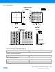
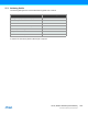
Table 38-1. Power Supply Connections, V
DDCORE
From Internal Regulator (Continued)
Signal Name Recommended Pin Connection Description
GND
VREFA
EXTERNAL
REFERENCE 1
4.7μF 100nF
GND
VREFB
EXTERNAL
REFERENCE 2
4.7μF 100nF
Close to device
(for every pin)