
Integration Guide
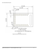
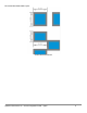
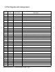

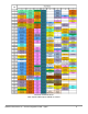

4.Pad Signals and Assignment
Module
Pad No.
Name
Pin Function
Description
1
GND
Power
Ground
2
GPIO20
SWDCK
JTAG single wire clock
3
GPIO49
RX0 Bootload
RX pin for serial bootloading
4
GPIO39
5
GPIO40
6
GPIO9
7
BOOT
Bootload
Hold pin high during reset to initiate bootloader
8
GPIO10
9
GPIO48
TX0 Bootload
TX pin for serial bootloading
10
GPIO21
SWDIO
JTAG single wire I/O
11
GPIO8
12
GPIO5
13
GPIO7
14
GPIO35
All GPIOs have up to 8 possible functions ranging from I2C,
15
GPIO4
SPI, PDM, SCC, UART, I2S, and clock sources. Please
16
GPIO24
see the Apollo3 datasheet for a complete listing of capabilities.
17
GPIO22
18
GPIO23
19
GPIO27
20
GPIO14
21
GPIO28
22
GND
Power
23
GPIO6
24
GPIO32
25
GPIO25
26
GPIO12
27
GPIO26
28
GPIO13
29
GPIO15
30
GPIO33
31
GPIO34
32
GPIO11
33
GPIO29
SparkFun Electronics Inc - Artemis Integration Guide - 1p0p3 7