
User Manual

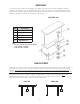

END STOPS
RUNWAY TRACK
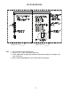
EXAMPLE
RUNWAY TRACK
12’
9’
15
’
C
B
A
6
The exact span of the crane may vary from the design span. We recommend installing the track on one side
m
aking sure that the track is straight and level. Lay one or two sections of the track down at the design span,
assemble crane on the tracks following assembly instructions and operate the crane back and forth a few
t
imes, being careful not to run the crane off the tracks. The loose sections of track will float and set the track
to the crane span. Once the operating span is determined, attach all the other sections of track to the floor
making sure the track is straight, level, parallel, and at the same elevation as the first track. The end stops
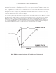
should be set square with the 3-4-5 right triangle. The sides and the hypotenuse can be multiplied by any
convenient number such as three used in the example.
Set one end stop at point A, measure along runway track nine feet from point A to point B. With B as a center
and fifteen feet as a radius, draw a circular arc on the floor, with point A as a center and 12 ft. as a radius.
Draw a circular arc on the floor intersecting the other arc at C. A line running through points A and C is
perpendicular, or square, with the runway track. Extend this line to the other runway track to locate the end
stop on that runway. Repeat the process at the other end of the runway, or measure along each runway the
same distance from these end stops for locating the stops at the other end of the runways.
NOTE: SPANCO recommends lagging with 3/8” lag bolts every 3’-0” staggered.
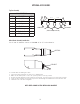
V-GROOVE INSTALLATION INSTRUCTIONS