
User Manual

4
1. For assembly, when possible, select an area under an overhead hoist, or where a lift truck can
be used to raise the I-beam. Be sure there is no machinery or clutter nearby that will hamper
free movement. All personnel should be wearing applicable safety gear, such as hard hats,
safety shoes, and safety glasses.
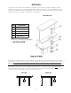
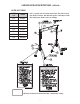
2. Lay both “A” frames flat on the floor, and slide upright tube into top of center tube. Upright
tube should then be pinned into its lowest position, making sure that load pin is fully engaged.
Top plate (and extension tube, if required) should be pinned also at this time with cotterless
hitch pins.
3. The caster wheels should then be locked in position parallel to the “A” frame. This will prevent
the frame assembly from rolling away when lifted to the upright position.
4. Using an overhead hoist or lift truck, lift the I-beam to the gantry's minimum height. Be sure
that the capacity rating is right side up and legible.
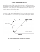
5. Lift one end of the frame assembly into position under one end of the I-beam, and bolt I-beam
to top plate of the upright with the hardware supplied. Be sure the lifting lug is on the outside
of the frame assembly, not facing the I-beam. Next, raise into position the other end frame and
bolt together as above.
6. Testing. We certify that the equipment referenced in this manual is in conformance with our
interpretation of applicable CMAA 74, ANSI B30.17, AISC ASD 9th Edition, and AWS D1.2.
This equipment is designed and manufactured to the rated capacity marked on the equipment
with due allowances for safety factors. It is recommended that a person appointed by the owner,
under the direction of a qualified technical person, shall perform a load test of 125% of the
rated capacity before placing the unit into service. See the latest edition of ANSI B30.17 for
clarification of details related to rated load tests.
7. Your SPANCO gantry is now ready to use, and you can now adjust the I-beam to desired height.
8. First secure the trolley and hoist in the center of the I-beam. To raise or lower unit height,
simply hang the optional “LUG-ALL” winch kit (if ordered with the gantry), or any other type of
“come-along”, from the lifting lug at the top of the A-frame. Now pull the bottom hook of the
“LUG-ALL” winch down and hook it under the end of the upright tube. By raising the upright
slightly, you can now pull back the spring-loaded adjustment pin. Secure the adjustment pin in
the lockout position. By operating the “LUG-ALL”, you can raise or lower the height of the
gantry. When desired height is reached, release the load pin. The load pin will self locate the
hole in the upright. Be sure the load pin is in the full lock-in position.
NOTE: This operation requires a “LUG-ALL” winch on each end of the unit. Both ends must be raised or lowered at the
same time. Never adjust gantry while it is supporting a load. Make sure that the “LUG-ALL” or “come-along” used for
height adjustment has a combined capacity rating equal to the weight of the I-beam and any hoist trolley that is
suspended from the I-beam.
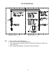
INSTALLATION