Manual No. 103-0008 REV. 08/14 Installation and Maintenance Manual for SPANCO ® A Series Aluminum Gantry Cranes ISO 9001 REGISTERED © SPANCO, Inc.
TABLE OF CONTENTS Warnings.................................................................................................................... 3 Installation................................................................................................................. 4 Maintenance............................................................................................................... 5 Span Adjustment...................................................................................................
INSTALLATION 1. For assembly, when possible, select an area under an overhead hoist, or where a lift truck can be used to raise the I-beam. Be sure there is no machinery or clutter nearby that will hamper free movement. All personnel should be wearing applicable safety gear, such as hard hats, safety shoes, and safety glasses. 2. Lay both “A” frames flat on the floor, and slide upright tube into top of center tube.
MAINTENANCE To ensure the safe operation of your gantry, periodically inspect it for bent, broken, damaged, corroded, cracked or missing parts. The only regular maintenance that is required is to check bolt tightness and to lubricate the casters through the grease fittings that are provided. Casters are prelubricated at the factory, but when lubrication is needed use NLGI No.1 or No.2 grease.
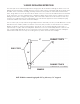
V-GROOVE INSTALLATION INSTRUCTIONS The exact span of the crane may vary from the design span. We recommend installing the track on one side making sure that the track is straight and level. Lay one or two sections of the track down at the design span, assemble crane on the tracks following assembly instructions and operate the crane back and forth a few times, being careful not to run the crane off the tracks. The loose sections of track will float and set the track to the crane span.
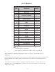
V-GROOVE INSTALLATION INSTRUCTIONS continued... CASTER BOLT TORQUE FASTENER SIZE TORQUE 1/4” 10 ft./lbs. 5/16” 19 ft./lbs. 3/8” 33 ft./lbs. 7/16” 54 ft./lbs. 1/2” 58 ft./lbs. 9/16” 114 ft./lbs. 5/8” 162 ft./lbs. 3/4” 288 ft./lbs. 3 This is a general chart of fastener torque values. This table is based upon Grade 5 fasteners. Note that lower grades of bolts may not take these high torques. Reduce values accordingly. t 2 and 3 ton models are manufactured with “rounded edge” tubing.
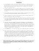
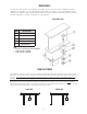
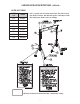
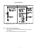
BILL OF MATERIALS BILL OF MATERIALS ITEM# DESCRIPTION QUANTITY 1 I-Beam 1 2 Upright Tube 2 3 End Frame/A Frame 2 4 2’ Extension (if required**) 2 5 Top Plate** 2 6 Cotterless Hitch Pin 2 15 Swivel Lock 4 16 Caster 4 17 Flat Washer 16 18 Lock Washer 16 19 Hex Nut 16 20 Hex Bolt 16 27 Clipped Washer 8* 28 Hex Bolt 8 29 Lock Washer 8 30 Hex Nut 8 31 I-Beam Clamp 8 32 Optional LUG-ALL Winch Kit 2 33 Safety Instruction 2 34 Safety Instruction 2 45 C
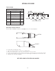
OPTIONAL ACCESSORIES Tagline Assembly BILL OF MATERIALS ITEM DESCRIPTION QTY 7 Cable Ties 5 6 Hex Nuts 4 5 Pulleys 5 4 Eye Bolts 2 3 Cable Clamps 2 2 Tagline Cable 1 1 Trolley Stops 2 4 6 3 5' - 0" 5' - 0" 2 7 1 5 TO EQUIPMENT FROM SUPPLY (CONDUCTOR NOT SUPPLIED) Wheel Brake Assembly Installation For 6” and 8” diameter casters on SPANCO “A” & “E” Series Gantries PEDAL BRAKE To 1. 2. 3. 4. 5.
LIFT KIT INSTRUCTIONS KITS WITHOUT ADAPTER LUG KITS WITH ADAPTER LUG NOTE: 1. To be used under no load conditions only. 2. For use on “A” or “ALU” series gantry cranes only. 3. For kits supplied with an adapter lug, DO NOT use without winch adapter lug or damage to the crane could result. 4. Before removing LUG-ALL® winch, ensure that load pin is fully engaged.
SPANCO, Inc. 604 Hemlock Road Morgantown, PA, 19543 Toll Free: 800-869-2080 Local: 610-286-7200 Fax: 610-286-0085 Spanco.