
Install Manual


16SPAN Drive Installation Manual Installation |
NOTE: Keep track of circuit labeling. This information
will be required during commissioning.
NOTE: To insert wiring into RS485 terminal on the SPAN
Panel, use a 2mm at head driver to depress the tab
while inserting stripped wire.
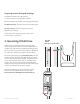
6. Connection to SPAN Panel
• Ensure that the breaker in SPAN is turned o. Note that there
is no particular location for the breaker in the SPAN Panel. Any
location will work.
• Make the L1, L2, and GND connections from SPAN Drive to the
2-pole breaker and GND in the SPAN Panel.
• Connect the communication wiring from SPAN Drive to
the RS485-1 terminal in the SPAN Panel (see image below).
RS485-G optional, but recommended to connect Drain wire to
Drive and Panel RS485-G terminals for best signal integrity.
WARNING: Risk of electric shock. Make sure power is turned o while connecting SPAN Drive
to the SPAN Panel. Always make sure all electrical equipment is safely de-energized before
beginning work.
WARNING: Ensure all power and ground connections, especially those at the breaker and bus bar,
are clean and tight. Remove all oxide from all conductors and terminals before connecting wiring.
• 90° C CU only
• Leave 6” service loop
• Use min 300V rated comms
shielded 2-wire twisted pair
• RS485-G optional, recom-
mended to connect Drain
wire for best signal integrity
SPAN Drive
GND
L1
L2
328’ (100M) Max
SPAN Panel
3/4 – 1” Conduit
1A
1B-
1G