
Install Manual


14SPAN Drive Installation Manual Installation |
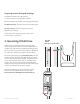
Communication wiring
Connect the communication wires according to the diagram below. Use minimum 300 V rated, 24–16 AWG,
shielded, twisted-pair, copper conductors only for communication wiring. Strip 3/8” (10mm) of insulation o
each wire and fully insert into the terminal. RS485-G optional, but recommended to connect Drain wire to
Drive and Panel RS485-G terminals for best signal integrity.
When only installing one SPAN Drive, leave the terminating resistor as is. If installing multiple chargers, re-
move the terminating resistor on all units except for the last unit the chain.
NOTE: If cable assembly such as MC Cable or NM Cable (Romex) is used, communication
wiring can be run separately using the center knockout and cable tie mounting point for
additional strain relief.
Terminating resistor.
Leave only for the
last device in chain.
NOTE: To insert wiring into RS485 terminal on the
SPAN Drive, rst take out the mating connector.
Then use wire strippers to depress the tab while
inserting stripped wire.