
Install Manual


13SPAN Drive Installation Manual Installation |
4. Electrical wiring
AC Power Wiring
Insert the AC power conductors either through the
bottom or rear entry opening in SPAN Drive. Ensure
there’s enough length for a 6” service loop in the
enclosure, as well as to easily connect the wires into
the lever lock terminal. If using a conduit connection,
pull the wiring through before connecting the conduit.
Use appropriate cable glands, bushings, or ttings
to secure the wiring in place and protect from water
and debris. Ensure that bushings are in place to avoid
damage to conductors and ground wire when pulled
into the enclosure.
Ensure the electrical panel supports a 120/240V
dedicated circuit with a 2-pole circuit breaker, rated
for the selected amperage (see following section Rated
Current Adjustment).
The voltage between the hot wires (L1 and L2) must
be 208/240V. Only L1, L2, and GND conductors are
connected, no Neutral.
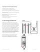
Connect the AC power conductors according to the
adjacent diagram. Use 90°C copper conductors only
within the wire size range of 10-6 AWG. Strip ½”
(13mm) of insulation o each wire and fully insert into
the lever lock terminal. Press the lever down until it
snaps into place for each wire. Be careful of ngers,
as the white levers are a pinch point.
Perform a tug test after inserting each wire and closing
the lever lock to ensure the connection is solid.
CAUTION: Follow guidance in NEC Chapter 3 and any local AHJ requirements for cable type
selection. Consider exterior surface and ush mounted installations as wet/damp conditions
and use conduit accordingly. When installed in wet/damp locations cable routed through the
bottom face must be wet- or damp-rated.
NOTE: For bottom wire entry, if installing ttings with a set screw, ensure that the screw
is positioned to avoid interference with the lower plastic cover.