
User's Manual


Table Of Contents
- Telemetry Transmitter
- Table of Contents
- Conventions Used in This Manual 1-1
- Nurses 1-7
- Monitor Technicians 1-7
- Biomedical Engineers 1-7
- Physicians 1-7
- Patients 1-7
- Sources of Interference 1-8
- Potential Sources of Damage 1-8
- Optional Leadwire Grouper 2-3
- Leadwire Color Codes 2-4
- Telemetry Channel Label 2-5
- Adult Electrode Placement 3-3
- Lead Fault Indication 3-4
- Noise Detection 3-4
- False Alarms 3-5
- Traditional Pulse Oximetry 3-5
- Electrodes, Leadwires, Sensors, and Sensor Cables 3-7
- Electrodes, Leadwires, Sensors and Sensor Cables 3-8
- Spacelabs Healthcare Technology 3-13
- Additional Information for Telemetry Products 3-13
- Telemetry 3-13
- Heart Rate Averaging 3-13
- Spacelabs Healthcare SpO2 Sensors 3-18
- Additional Information 3-18
- Transmitter Batteries 4-1
- Host Monitors 4-2
- Telemetry Receiver Module 4-2
- Assigning a Telemetry Channel 4-3
- Top, Front and Bottom View (96281-C) 4-4
- Rear View (96281-C) 4-5
- Front View (96281-A) 4-6
- Battery Compartment (96281-A, 96281-B, 96281-C) 4-7
- ECG 4-12
- SpO2 4-14
- Cleaning/Disinfecting 5-1
- Recommended Cleaning Solutions 5-2
- Basic Cleaning and Low-level Disinfection 5-3
- Cleaning ECG Leadwires 5-3
- Cleaning Buttons 5-3
- Cleaning the Battery Cover 5-3
- Table 1—Electromagnetic Emmissions A-1
- Table 2—Electromagnetic Immunity A-2
- Table 2—Electromagnetic Immunity (continued) A-3
- Table 3—Separation Distances A-4
- Introduction
- About the Transmitters
- ECG and SpO2
- ECG Overview
- Patient Preparation and Electrode Application
- To Set Up ECG Monitoring
- ECG Problem Solving
- SpO2 Overview
- Warnings and Cautions for SpO2
- Setting Up SpO2 Monitoring
- Ensuring Accurate SpO2 Monitoring
- SpO2 and Pulse Rate Specifications
- Using the Sensorwatch Feature
- Enabling and Adjusting Alarms
- Data Averaging
- Display Details at the Host Monitor
- Printing SpO2 Waveforms
- SpO2 Messages at the Host Monitor
- Sensors
- SpO2 Alarm Delays
- SpO2 Troubleshooting Guide
- Basic Operations
- Getting Started
- Basic Components
- Selecting Options for Leads
- Basic User Actions
- Basic Modes of Operation
- View Mode
- Status Messages at the Host Monitor
- Telemetry Transmitter with ECG Only Troubleshooting Guide
- Telemetry Transmitter with Display Troubleshooting Guide
- Telemetry Transmitter with Display and SpO2 Troubleshooting Guide
- Cleaning, Disinfecting, and Sterilization
- Appendix A — Guidance and Manufacturer’s Declaration
- Appendix B — Symbols
B ASIC OPERATIONS
TELEMETRY TRANSMITTER (96281) OPERATIONS MANUAL 4-12
View Mode
View Mode is available only with transmitters that include a display (96281-B or 96281-C), so it is not
applicable to the 96281-A telemetry transmitter.
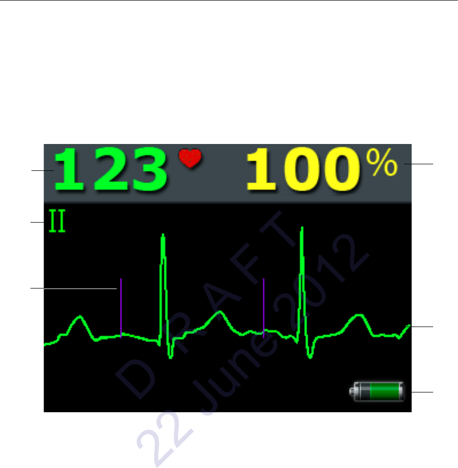
ECG
ECG data is obtained directly from the patient connection and shows on the transmitter LCD as shown
in
Figure 4-6, depending on configuration of leads and available parameters.
Figure 4-6: Paced ECG and SpO
2
display on the 96281-C
1 SpO
2
saturation percentage (available on 96281-C only)
2 ECG waveform
3 Battery charge indicator (shows the battery state)
4 Pacing marker
5 Shown lead indicator
6 Heart rate derived from ECG (indicated by solid heart icon)
Note:
The AriaTele acquires and transmits ECG data in samples. In addition, it may show the ECG
waveform on its optional display. When the AriaTele acquires an ECG sample that it detects as
possessing a pacing pulse, it does two things:
1
2
3
5
6
4
D R A F T
22 June 2012