
User's Manual


Table Of Contents
- Telemetry Transmitter
- Table of Contents
- Conventions Used in This Manual 1-1
- Nurses 1-7
- Monitor Technicians 1-7
- Biomedical Engineers 1-7
- Physicians 1-7
- Patients 1-7
- Sources of Interference 1-8
- Potential Sources of Damage 1-8
- Optional Leadwire Grouper 2-3
- Leadwire Color Codes 2-4
- Telemetry Channel Label 2-5
- Adult Electrode Placement 3-3
- Lead Fault Indication 3-4
- Noise Detection 3-4
- False Alarms 3-5
- Traditional Pulse Oximetry 3-5
- Electrodes, Leadwires, Sensors, and Sensor Cables 3-7
- Electrodes, Leadwires, Sensors and Sensor Cables 3-8
- Spacelabs Healthcare Technology 3-13
- Additional Information for Telemetry Products 3-13
- Telemetry 3-13
- Heart Rate Averaging 3-13
- Spacelabs Healthcare SpO2 Sensors 3-18
- Additional Information 3-18
- Transmitter Batteries 4-1
- Host Monitors 4-2
- Telemetry Receiver Module 4-2
- Assigning a Telemetry Channel 4-3
- Top, Front and Bottom View (96281-C) 4-4
- Rear View (96281-C) 4-5
- Front View (96281-A) 4-6
- Battery Compartment (96281-A, 96281-B, 96281-C) 4-7
- ECG 4-12
- SpO2 4-14
- Cleaning/Disinfecting 5-1
- Recommended Cleaning Solutions 5-2
- Basic Cleaning and Low-level Disinfection 5-3
- Cleaning ECG Leadwires 5-3
- Cleaning Buttons 5-3
- Cleaning the Battery Cover 5-3
- Table 1—Electromagnetic Emmissions A-1
- Table 2—Electromagnetic Immunity A-2
- Table 2—Electromagnetic Immunity (continued) A-3
- Table 3—Separation Distances A-4
- Introduction
- About the Transmitters
- ECG and SpO2
- ECG Overview
- Patient Preparation and Electrode Application
- To Set Up ECG Monitoring
- ECG Problem Solving
- SpO2 Overview
- Warnings and Cautions for SpO2
- Setting Up SpO2 Monitoring
- Ensuring Accurate SpO2 Monitoring
- SpO2 and Pulse Rate Specifications
- Using the Sensorwatch Feature
- Enabling and Adjusting Alarms
- Data Averaging
- Display Details at the Host Monitor
- Printing SpO2 Waveforms
- SpO2 Messages at the Host Monitor
- Sensors
- SpO2 Alarm Delays
- SpO2 Troubleshooting Guide
- Basic Operations
- Getting Started
- Basic Components
- Selecting Options for Leads
- Basic User Actions
- Basic Modes of Operation
- View Mode
- Status Messages at the Host Monitor
- Telemetry Transmitter with ECG Only Troubleshooting Guide
- Telemetry Transmitter with Display Troubleshooting Guide
- Telemetry Transmitter with Display and SpO2 Troubleshooting Guide
- Cleaning, Disinfecting, and Sterilization
- Appendix A — Guidance and Manufacturer’s Declaration
- Appendix B — Symbols
A BOUT THE TRANSMITTERS
TELEMETRY TRANSMITTER (96281) OPERATIONS MANUAL 2-4
Labeling
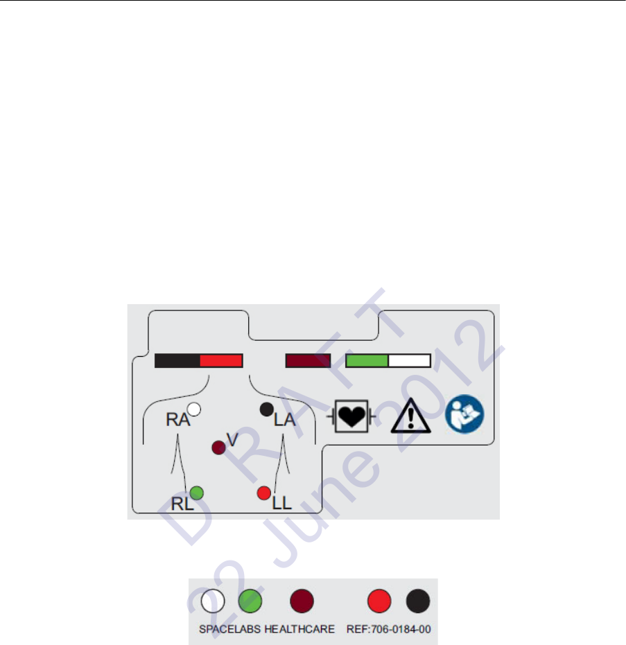
Leadwire Color Codes
Both AHA/AAMI or IEC color codes are used on the leadwires and the transmitter labeling. The
color codes for your transmitter and leadwires are based on the preference in your locale. These
color variations are shown on the back label of the transmitter, front of the leadwire grouper, and
on the individual ECG connectors and leadwires. This is to assist in connecting the leadwires to the
correct input.
1 Match the color of the ECG leadwire to the color label on the leadwires grouper
2 Match the color label on the leadwires grouper to the color label on the transmitter
AHA/AAMI Leadwire Labels
Figure 2-4: 5-lead AHA/AAMI color codes label on rear of transmitter
Figure 2-5: 5-way AHA/AAMI label on front of grouper
D R A F T
22 June 2012