SY-K7VTA PRO Motherboard **************************************************** AMD® Athlon/Duron Processor supported VIA KT133A AGP/PCI Motherboard 266 MHz Front Side Bus supported ATX Form Factor **************************************************** User's Manual
SOYO™ SY-K7VTA PRO Copyright © 2001 by Soyo Computer Inc. Trademarks: Soyo is the registered trademark of Soyo Computer Inc. All trademarks are the properties of their owners. Product Rights: All names of the product and corporate mentioned in this publication are used for identification purposes only. The registered trademarks and copyrights belong to their respective companies. Copyright Notice: All rights reserved. This manual has been copyrighted by Soyo Computer Inc.
Table of Contents SY-K7VTA PRO Table of Contents CHAPTER 1 MOTHERBOARD DESCRIPTION .............................1 1-1 INTRODUCTION ...........................................................1 1-2 1-3 1-4 1-5 1-6 1-7 1-8 1-9 KEY FEATURES ............................................................1 ELECTROSTATIC DISCHARGE PRECAUTIONS ........5 SY-K7VTA PRO MOTHERBOARD LAYOUT...............6 SY-K7VTA PRO MOTHERBOARD COMPONENTS......7 MICROPROCESSOR......................................................
Table of Contents 3-1 3-2 3-3 3-4 3-5 3-6 3-7 3-8 3-9 3-10 3-11 3-12 3-13 3-14 SY-K7VTA PRO SOYO COMBO SETUP.................................................54 STANDARD CMOS SETUP ..........................................57 ADVANCED BIOS FEATURES.....................................60 ADVANCED CHIPSET FEATURES..............................64 INTEGRATED PERIPHERALS .....................................69 POWER MANAGEMENT SETUP ................................74 PNP/PCI CONFIGURATION SETUP.................
Motherboard Description SY-K7VTA PRO Chapter 1 MOTHERBOARD DESCRIPTION 1-1 INTRODUCTION The SY-K7VTA PRO AGP/PCI/ISA Motherboard is a high-performance Socket 462 ATX form-factor system board. The SY-K7VTA PRO uses VIA Chipset technology and supports Socket 462 class processors. This Motherboard is fully compatible with industry standards and adds many technical enhancements.
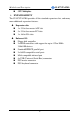
Motherboard Description n Ø SY-K7VTA PRO CPU Multiplier EXPANDABILITY The SY-K7VTA PRO provides all the standard expansion slots, and many more additional expansion features: u Expansion slots n 1 x 32-bit bus master AGP slot n 5 x 32-bit bus master PCI slots n 1 x 16-bit ISA slots u n n n n n n n n Enhanced IO Floppy disk controller 2x EIDE controllers with support for up to 4 Ultra DMA 33/66/100 devices Standard/EPP/ECP parallel port 2x 16550 compatible serial ports IrDA compatible infrared port 4
Motherboard Description Ø SY-K7VTA PRO ADVANCED FUNCTIONS The SY-K7VTA PRO supports advanced functions such as: n Wake-On-LAN Supports Wake-On-LAN (Some advanced network cards can wake the system up over the network, the WOL connector is provided by the SY-K7VTA PRO to support this function). n Multiple boot The SY-K7VTA PRO supports booting from devices such as CDROM, FLOPPY DRIVE & HDD, LS120, SCSI, ZIP.
Motherboard Description Ø USER FRIENDLY n n n Ø SY-K7VTA PRO SOYO Combo Setup Jumperless design You can set up the following options trough the BIOS setting CPU FSB frequency CPU multiplier by H/W switch CPU Vcore voltage PCI clock AGP Clock SDRAM Clock Voice Doctor If the system does not boot-up properly, the Voice Doctor will inform the user by voice through internal/external speaker at what point in boot-up sequence the problem arises.
Motherboard Description Ø SY-K7VTA PRO HANDLING THE MOTHERBOARD To avoid damage to your Motherboard, follow these simple rules while unpacking: Ø Before handling the Motherboard, ground yourself by grasping an unpainted portion of the system's metal chassis. Ø Remove the Motherboard from its anti-static packaging. Hold the Ø Motherboard by the edges and avoid touching its components. Check the Motherboard for damage. If any chip appears loose, press carefully to seat it firmly in its socket.
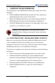
Motherboard Description SY-K7VTA PRO 1-4 SY-K7VTA PRO MOTHERBOARD LAYOUT PS/2 KB PS/2 Mouse Connector Connector 3 1 J2 USB 1_2 PRT 3 COM1 1 FJ1 RJ1 COM2 3 ATX Power 1 GAME SDRAM LINE-OUT FJ2 1 3 J3 ® LINE-IN VT8363A MIC-IN 4 SDRAM 1 CDIN1 AGP Slot 1 Sigmatel STAC9700 3 IDE 1 IDE 2 FLP JP5 PCI Slot #1 ® PCI Slot #2 VT82C686B 3V Lithium Battery PCI Slot #3 1 3 JP7 PCI Slot #4 PCI Slot #5 ISA Slot Flash BIOS Back Panel SY-K7VTA PRO Platform 6
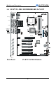
Motherboard Description SY-K7VTA PRO 1-5 SY-K7VTA PRO MOTHERBOARD COMPONENTS A B C D E F G H AB I J K SDRAM ® SDRAM L AA Z M Sigmatel STAC9700 N O ® P Y Q X R S T W V U 7
Motherboard Description A B C D E F G H I J K L M N O P Q R S T U V W X Y Z AA AB SY-K7VTA PRO ATX Power Supply Connector Via VT8363A North Bridge chip Chipset Cooling Fan Connector Socket 462 Connector Frequency Multiplier setting Jumper DIMM Banks CPU Cooling Fan Connector CPU FSB setting Jumper Ratio adjustment setting switch Frequency Multiplier setting Jumper Bus Mastering E-IDE/ATAPI Ports Floppy Disk Drive (FDD) Port CMOS Clear Jumper 32-bit AGP 1X/2X/4X Slot Via VT82C686B South Bridge Chip USB3_4
Motherboard Description SY-K7VTA PRO 1-6 MICROPROCESSOR The motherboard supports a single Socket 462 processor. The processor’s VID pins automatically program the voltage regulator on the motherboard to the required processor voltage. In addition, the front side bus speed (200 MHz ) is automatically selected. The motherboard supports all current Socket 462 processor speeds, voltages, and bus frequencies. 1-6.1 Microprocessor Packaging The CPU is packaged in a 462 pin PGA package.
Motherboard Description SY-K7VTA PRO 1-7 MEMORY 1-7.1 Main Memory The motherboard has three DIMM sockets. SDRAM can be installed in one, two, or three sockets. Using the serial presence detect (SPD) data structure, programmed into an E²PROM on the DIMM, the BIOS can determine the SDRAM’s size and speed. Minimum DIMM memory size is 8 MB; maximum DIMM memory size is 256/512 MB. Memory size and speed can vary between sockets.
Motherboard Description SY-K7VTA PRO Seamless DRAM command scheduling for maximum DRAM bus utilization (e.g.
Motherboard Description SY-K7VTA PRO 1-8 CHIPSET Ø VT8363A The KT133A chip set consists of the VT8363A system controller (552 pin BGA) and the VT82C686B PCI to ISA bridge (352 pin BGA). The system controller provides superior performance between the CPU, DRAM, AGP bus, and PCI bus with pipelined, burst, and concurrent operation. The VT8363A support six banks of DRAMs up to 1.5GB.
Motherboard Description SY-K7VTA PRO buffers and sixteen levels (doublewords) of prefetch buffers are included for concurrent PCI bus and DRAM/cache accesses. The chip also supports enhanced PCI bus commands such as Memory-Read-Line, Memory-Read-Multiple and Memory-Write-Invalid commands to minimize snoop overhead.
Motherboard Description SY-K7VTA PRO software can run transparently in non-USB-aware operating system environment. 3) Keyboard controller with PS2 mouse support. 4) Real Time Clock with 256 byte extended CMOS. In addition to the standard ISA RTC functionality, the integrated RTC also includes the date alarm, century field, and other enhancements for compatibility with the ACPI standard.
Motherboard Description SY-K7VTA PRO level triggered interrupts channel by channel. The integrated DMA controller supports type F DMA in addition to standard ISA DMA modes. Compliant with the PCI2.2 specification, the VT83C686A supports delayed transactions and remote power management so that slower ISA peripherals do not block the traffic of the PCI bus. Special circuitry is built in to allow concurrent operation without causing dead lock even in a PCIto PCI bridge environment.
Motherboard Description SY-K7VTA PRO Data rates up to 1Mbps Perpendicular recording driver support Two FDDs with drive swap support Plug and play with 48 base IO address, 12 IRQ and 4 DMA options The Setup program provides configuration option for the I/O controller. 1-9.1 Serial Ports The motherboard has two 9-pin D-Sub serial port connectors located on the back panel. The NS16C5450-compatible UARTs support data transfers at speeds up to 115.2 Kbits/sec with BIOS support. 1-9.
Motherboard Description SY-K7VTA PRO 1-9.4 PS/2 Keyboard and Mouse Interface PS/2 keyboard and mouse connectors are located on the back panel of the motherboard. The +5 V lines to keyboard and mouse connectors are protected with a fuse that prevents motherboard components from being damaged when an over-current condition occurs. Note The mouse and keyboard can be plugged into either PS/2 connector. Power to the computer should be turned off before a keyboard or mouse is connected or disconnected.
Motherboard Description SY-K7VTA PRO subsystem include: Ø An integrated ambient temperature sensor Ø Fan speed sensors, which monitor the fan 1 and fan 2 connector. Ø Power supply voltage monitoring to detect levels above or below acceptable values When suggested ratings for temperature, fan speed, or voltage are exceeded, an interrupt is activated. The hardware monitor component connects to the SMBus.
BIOS Setup Utility SY-K7VTA PRO Chapter 2 HARDWARE INSTALLATION Congratulations on your purchase of SY-K7VTA PRO Motherboard. You are about to install and connect your new Motherboard. Note: Do not unpack the Motherboard from its protective antistatic packaging until you have made the following preparations. 2-1 PREPARATIONS Gather and prepare all the following hardware equipment to complete the installation successfully: 1. Socket 462 processor with built-in CPU cooling fan (boxed type).
BIOS Setup Utility 2-2 SY-K7VTA PRO UNPACKING THE MOTHERBOARD When unpacking the Motherboard, check for the following items: u The SY-K7VTA PRO KT133A AGP/PCI/ISA Motherboard u The Quick Start Guide u The Installation CD-ROM u SOYO Bonus Pack CD-ROM u One IDE Device ATA 66 Flat Cable u One Floppy Disk Drive Flat Cable u One Heat Sink Compound Warning: Do not unpack the Motherboard from its anti-static packaging until you are ready to install it.
BIOS Setup Utility SY-K7VTA PRO 2-3 INSTALLATION GUIDE We will now begin the installation of the Motherboard. Please follow the step-by-step procedure designed to lead you to a complete and correct installation. Warning: Turn off the power to the Motherboard, system chassis, and peripheral devices before performing any work on the Motherboard or system.
BIOS Setup Utility SY-K7VTA PRO 2-3.1 CPU Installation Your SY-K7VTA PRO motherboard comes with a CPU retention set kit. The retention set is used to hold the processor attached to the Socket 462 CPU connector on the motherboard. FOC ( Fan-Off Control ) The newly designed SOYO “FOC” is based on the concept of total protection for CPU, which is very different from currently seen on the market. The H/W control function is used to see a passive security system of monitoring and warning.
BIOS Setup Utility SY-K7VTA PRO sensor pins, to avoid the power off. Users may press the “Insert” key to jump over the “Power Off” mode; go to the BIOS and disable “FOC”. Now system can be booted normally. 4. The power connector of the CPU fan must be connected to the specified “CPU Fan Connector” on the motherboard to secure the normal functioning of the system. We provide the following User-Friendly protection features: 1.
BIOS Setup Utility SY-K7VTA PRO Follow these instructions to install your Socket 462 processor correctly. 1. Lift the socket handle up to a vertical position. 2. Align the blunt edge of the CPU with the matching pinhole distinctive edge on the socket.
BIOS Setup Utility SY-K7VTA PRO 3. Seat the processor in the socket completely and without forcing. 4. Then close the socket handle to secure the CPU in place. Remember to connect the CPU Cooling Fan to the appropriate power connector on the Motherboard. The fan is a key component that will ensure system stability. The fan prevents overheating, therefore prolonging the life of your CPU.
BIOS Setup Utility SY-K7VTA PRO 2-3.2 SDRAM Memory Module Installation SDRAM ® SDRAM Sigmatel STAC9700 ® Your board comes with two DIMM sockets, providing support for up to 1.5GB of main memory using unbuffered and registered DIMM modules from 8MB to 512MB. On this motherboard, DRAM speed can be set independent from the CPU front side bus speed. Depending on the DRAM clock speed setting in the BIOS setup (Chapter 3), appropriate memory modules must be used.
BIOS Setup Utility SY-K7VTA PRO Memory Configuration Table Number of Memory Modules DIMM 1 DIMM 2 DIMM 3 RAM Type SDRAM/VCM SDRAM Memory Module Size (MB) 32/64/128/256/512 MB 27
BIOS Setup Utility SY-K7VTA PRO 2-3.3 Motherboard Connector SDRAM ® SDRAM Sigmatel STAC9700 ® IDE 1 IDE 2 Primary IDE Secondary IDE Pin-1 2-3.3.1 IDE Device Installation (HDD, CD-ROM) This Motherboard offers two primary and secondary IDE device connectors (IDE1, IDE2). It can support up to four high-speed Ultra DMA 33/66/100HDD or CD-ROM.
BIOS Setup Utility SY-K7VTA PRO 2-3.3.2 Floppy Drive Installation SDRAM ® SDRAM Pin -1 Sigmatel STAC9700 FDC Floppy Drive Connector ® The system supports 5 possible floppy drive types: 720 KB, 1.2 MB, 1.44 MB, 2.88 MB, and LS-120. Connect one side of the 34-pin flat cable to the floppy drive and plug the other end to the floppy drive connector on the Motherboard. This Motherboard can support up to 2 floppy drives.
BIOS Setup Utility SY-K7VTA PRO 2-3.3.3 Front Panel Connections + SDRAM ® + HDD LED _ Speaker _ _ STR LED + SDRAM PWRBT Sigmatel STAC9700 Power LED _ ® + Reset Plug the computer case's front panel devices to the corresponding headers on the Motherboard. 1. Power LED Please install according to the following pin assignment: pin 1,3 are for Power LED.
BIOS Setup Utility SY-K7VTA PRO 2. Reset Plug the Reset push-button cable into the 2-pin Reset header on the Motherboard. Pushing the Reset button on the front panel will cause the system to restart the boot-up sequence. PWRBT Pin Assignment 1 PW-BT GND 3. Speaker Attach the 4-pin PC speaker cable from the case to the Speaker header on the Motherboard. Speaker Pin Assignment _ + VCC NC NC Speaker out 4.
BIOS Setup Utility SY-K7VTA PRO 5. ATX Power On/Off Switch Attach the 2-pin momentary type switch to the PWRBT header for turning On or Off your ATX power supply. PWRBT Pin Assignment 1 Power On/Off GND 6. STR LED The STR LED is connected to the Voltage that feeds the DIMM sockets.
BIOS Setup Utility SY-K7VTA PRO 2-3.3.4 Back Panel Connections All external devices such as the PS/2 keyboard, PS/2 mouse, printer, modem, USB can be plugged directly onto the Motherboard back panel. Only after you have fixed and locked the Motherboard to the computer case can you start connecting the external peripheral devices. When connecting an external device, use the following figure to locate and identify which back panel connector to plug the device to.
BIOS Setup Utility SY-K7VTA PRO 1. Onboard Serial Ports COM1/COM2 External peripherals that use serial transmission scheme include: - serial mouse, - and modem. Plug the serial device cables directly into the COM1/COM2 9-pin male connectors located at the rear panel of the Motherboard. 2. Parallel Port PRT This parallel port is used to connect the printer or other parallel devices. Plug the parallel device cable into the 25-pin female connector located at the rear panel of the Motherboard. 3.
BIOS Setup Utility SY-K7VTA PRO 5. Universal Serial Bus USB1/USB2/(USB3, USB4) This Motherboard provides four USB ports for your additional devices. Plug the USB device jack into the available USB connector USB1 or USB2. Standard device drivers come with the Win98 for commonly used - USB devices. With Win95, use the flow UHCI specifications. To use USB devices under Win95, usually you have to install the device that driver comes with the USB device you have purchased.
BIOS Setup Utility SY-K7VTA PRO 2-3.3.5 Other Connections 1. Wake-On-LAN (WOL) Attach the 3-pin connector from the LAN card which supports the WakeOn-LAN (WOL) function to the JP10 header on the Motherboard. This WOL function lets users wake up the connected computer through the LAN card.
BIOS Setup Utility SY-K7VTA PRO 2. Infrared (SIRCON) Plug the 5-pin infrared device cable to the SIRCON header. This will enable the infrared transfer function. This Motherboard meets both the ASKIR and HPSIR specifications. Please install according to the following pin assignment: Standard Infrared (SIRCON) Connector SIRCON Pin Assignment 1 2 3 4 5 +5V IRRX GND IRTX 3. Other Display Cards Insert other types of VGA cards into the PCI or ISA expansion slots according to card specifications.
BIOS Setup Utility 4. SY-K7VTA PRO Cooling Fan Installation (1) CPU Cooling Fan After you have seated the CPU properly on the processor, attach the 3-pin fan cable to the CPUFAN connector on the Motherboard. The fan will stop when the system enters into Suspend Mode. (Suspend mode can be enabled from the BIOS Setup Utility, [POWER MANAGEMENT] menu.
BIOS Setup Utility SY-K7VTA PRO (2) Chassis Cooling Fan Some chassis also feature a cooling fan. This Motherboard features a CHAFAN connector to provide 12V power to the chassis fan. Connect the cable from the chassis fan to the CHAFAN 3-pin connector. Install according to the following pin assignment: Chassis Cooling Fan CHAFAN1 Pin Assignment 1 GND 2 12V 3 SENSOR (3) Chipset Cooling Fan Some chipset also feature a cooling fan.
BIOS Setup Utility SY-K7VTA PRO 5. CD Line-in (CDIN1) This Motherboard provides two CD-Line in connectors. Please connect the 4-pin audio cable from your CD-ROM drive to either CDIN1. (It fits in only one, depending on the cable that came with your CD-ROM drive) Please install according to the following pin assignment: CD-IN: CDIN1 4 Right 3 GND 2 GND 1 Left 2-3.3.6 AGP VGA Card Insert the AGP VGA card into the AGP slot.
BIOS Setup Utility SY-K7VTA PRO 2-3.3.7 AT X Power Supply Plug the connector from the power directly into the 20-pin male ATX PW connector on the Motherboard, as shown in the following figure. ATX Power SDRAM ® SDRAM Sigmatel STAC9700 ® Warning: Follow these precautions to preserve your Motherboard from any remnant currents when connecting to ATX power supply: Turn off the power supply and unplug the power cord of the ATX power supply before connecting to ATX PW connector.
BIOS Setup Utility SY-K7VTA PRO * Note: If you use the Wake-On-LAN (WOL) function, make sure the ATX power supply can support at least 720 mA on the 5V Standby lead (5VSB). Please install the ATX power according to the following pin assignment: ATX Power 12V 5VSB PW-OK GND 5V 5V -5V GND GND 5V GND 5V GND PS-ON GND GND 3.3V Ø Pay special care to the directionality. -12V 3.3V 3.3V 2-3.4 Jumper Setting 2-3.4.
BIOS Setup Utility SY-K7VTA PRO If you set ratio to manual and configure the RJ1 jumper to the settings that match your CPU speed as follow table. RJ1 5 5.5 6 6.5 7 7.5 8 8.5 1 on on on on off off off off 2 off off off off on on on on 3 on on off off on on off off 4 on off on off on off on off RJ1 9 9.5 10 10.5 11 11.5 12 12.
BIOS Setup Utility SY-K7VTA PRO 2-3.5 Voice Doctor If the system does not boot-up properly, the Voice Doctor will inform the user by voice through internal/external speaker at what point in boot-up sequence the problem arises. Below are the possible errors the user may encounter: 7. The Processor might be damage or not installed properly 8. 9. 10. 11. 12.
BIOS Setup Utility SY-K7VTA PRO 2-3.7 Power On You have now completed the hardware installation of your Motherboard successfully. 1. Turn the power on 2. To enter the BIOS Setup Utility, press the key while the system is performing the diagnostic checks, Note: If you have failed to enter the BIOS, wait until the boot up sequence is completed. Then push the RESET button and press key again at the beginning of boot-up, during diagnostic checks.
BIOS Setup Utility SY-K7VTA PRO 2-3.8 Quick BIOS Setup This Motherboard does not use any hardware jumpers to set the CPU frequency. Instead, CPU settings are software configurable with the BIOS [SOYO COMBO SETUP]. The [SOYO COMBO SETUP] menu combines the main parameters that you need to configure, all in one menu, for a quick setup in BIOS.
BIOS Setup Utility SY-K7VTA PRO 2-3.9 Troubleshooting at First Start Video (no display) related issues I built a new computer system using a Soyo board and nothing happens when turning it on, no video and no beeps from the PC speaker. What is happening and how can it be fixed? No screen and no beeps mean that your CPU and motherboard do not work at all. It could be that the CPU is not seated correctly or that a component on the M/B is grounded (shorted) with the case.
BIOS Setup Utility SY-K7VTA PRO My PCI VGA card works fine with my system, but when I put in a new AGP card, it does not give me any video. Is my AGP slot bad? This is a common problem with AGP video cards. The reason is that your AGP card did not get seated into the AGP slot fully and firmly. Please push your AGP card down into the socket real hard, it should snap twice. You may have to unscrew the AGP card to allow the card to go further down. Do take care not to damage the card by using too much force.
BIOS Setup Utility SY-K7VTA PRO What you need to do is to disable 'COM2' (or UART2 or serial port 2) in the bios under integrated peripheral setup. I have installed my modem drivers several times and I still cannot get my modem to work. Why? If you are sure that the modem driver has been installed correctly, then you need to install the south bridge driver from the SOYO CD, this is because Windows does not properly recognize relatively new chipsets. Audio Issues I do not get any sound from my sound card.
BIOS Setup Utility SY-K7VTA PRO This is because the recorder and microphone in the Windows are not enabled. Please go to sound properties and enable them. Lock up (freeze) When I boot up my system, everything works fine. It sees my CPU and memory, detects my hard drive, floppy drive and CD-ROM but locks up at "Verify DMI pool data... ", and it won’t go any further. What should I do? Please clear the CMOS via JP5 then choose 'load setup default' in the bios and save the bios and exit.
BIOS Setup Utility SY-K7VTA PRO Chapter 3 BIOS SETUP UTILITY This Motherboard's BIOS setup program uses the ROM PCI/ISA BIOS program from Award Software Inc. To enter the Award BIOS program's Main Menu: 1. Turn on or reboot the system. 2. After the diagnostic checks, press the [Del] key to enter the Award BIOS Setup Utility.
BIOS Setup Utility SY-K7VTA PRO Hot Keys: Function keys give you access to a group of commands throughout the BIOS utility. Function Command Description Gives the list of options available for each F1 General Help item. Previous Restore the old values. These are the values F5 Values that the user started the current session with. Load FailLoads all items with the most conservative F6 Safe Defaults values. Load F7 Optimized Loads all options with the optimize values.
BIOS Setup Utility SY-K7VTA PRO SAVE AND EXIT SETUP Select the [SAVE & EXIT SETUP] option from the Main Menu to save data to CMOS and exit the setup utility. This option saves all your changes and causes the system to reboot. R O M C M O S A W S T A N D A R D B IO S C M O S F E A T U R E S C H IP S E T P O W E R A R D P C I/IS A U T IL I T Y S O F T W A R E , IN C .
BIOS Setup Utility SY-K7VTA PRO 3-1 SOYO COMBO SETUP This Motherboard does not use any hardware jumpers to set the CPU frequency. Instead, CPU settings are software configurable with the BIOS [SOYO COMBO SETUP]. After the hardware installation is complete, turn the power switch on, then press the key during the system diagnostic checks to enter the Award BIOS Setup program. The CMOS SETUP UTILITY will display on screen.
BIOS Setup Utility SY-K7VTA PRO 3-1.1 Setting Disabled Auto Detect DIMM/PCI Clk Enabled Spread Spectrum Modulated Disabled Enabled Description Note For EMI test purpose. Default Default When using Spread Spectrum Modulated 1.5% or 6% for FCC or DOC testing. CPU Host/PCI Default 100/33 MHz Clock 109/36 MHz 110/36 MHz 111/37 MHz 113/37 MHz 115/38 MHz 117/39 MHz 120/40 MHz 101/33 MHz 102/34 MHz 103/34 MHz 105/35 MHz 107/35 MHz This item lists the Default CPU host clock and the PCI bus clock.
BIOS Setup Utility SY-K7VTA PRO 3-1.4 Quick Power On Self Test Setting Quick Power On Self Test Description Disabled Enabled Provides a fast POTS at boot-up. Note Default 3-1.
BIOS Setup Utility SY-K7VTA PRO 3-2 STANDARD CMOS SETUP Select the [STANDARD CMOS SETUP] option from the Main Menu and press [Enter] key. CMOS Setup Utility – Copyright ( C ) 1984-2000 Award Software Standard CMOS Features Date (mm:dd:yy) Time (hh:mm:ss) Tue, Jan 4 2000 1 : 22 : 12 4 IDE Primary Master 4 IDE Primary Slave 4 IDE Secondary Master 4 IDE Secondary Slave Maxtor 82160D2 None None NEC Drive A Drive B Floppy 3 Mode Support 1.44M, 3.5 in.
BIOS Setup Utility SY-K7VTA PRO 3-2.2 Hard Disks Type & Mode Choose the type and mode for the hard disks that you have already installed. Primary Setting Description Note (Secondary) Master & Slave IDE HDD Auto- Press Enter Detection IDE Primary Slave (User Type) Auto Access Mode Auto User None To auto-detect the HDD’s size, head …on this channel BIOS detects hard disk type Default automatically. User defines the type of hard disk. BIOS detects hard disk mode automatically.
BIOS Setup Utility SY-K7VTA PRO 3-2.4 Others Optional Setting Description Note Video EGA/VGA CGA 40 CGA 80 MONO (Monochrome) Select the video mode. Halt On ALL Errors No Errors All, But Keyboard All, But Diskette All, But Disk/Key When the BIOS detects system Default errors, this function will stop the system. Select which type of error will cause the system halt.
BIOS Setup Utility SY-K7VTA PRO 3-3 ADVANCED BIOS FEATURES Select the [Advanced BIOS Features] option from the Main Menu and press [Enter] key. CMOS Setup Utility – Copyright ( C ) 1984-2000 Award Software Advanced BIOS Features Virus Warning CPU Internal Cache External Cache Swap Floppy Drive Boot Up Floppy Seek Boot Up NumLock Status Gate A20 Option Typematic Rate Setting x Typematic Rate (Chars/Sec) x Typematic Delay (Msec) Security Option OS Select For DRAM > 64MB HDD S.M.A.R.T.
BIOS Setup Utility SY-K7VTA PRO 3-3.1 Virus Warning Setting Virus Warning Disabled Enabled Description Allows you to choose the VIRUS Warning feature for IDE Hard Disk boot sector protection. If this function is enabled and someone attempt to write data into this area, BIOS will show a warning message on screen and alarm beep. Note Default 3-3.2 Cache Memory Options Setting Description Note CPU Internal Cache Disabled Enabled Enables the CPU's internal Default cache.
BIOS Setup Utility SY-K7VTA PRO 3-3.5 Boot Up NumLock Status Setting Boot Up NumLock Status On Description Note Puts numeric keypad in Default NumLock mode at boot-up. Puts numeric keypad in arrow key mode at boot-up. Off 3-3.6 Gate A20 Options Setting Gate A20 Options Normal Fast Description Lets chipset control GateA20. A pin in the keyboard controller controls GateA20. Note Default 3-3.
BIOS Setup Utility SY-K7VTA PRO 3-3.8 Security Option Use this feature to prevent unauthorized system boot-up or use of BIOS Setup. The following table describes the security settings. Setting Description Security Option System Setup Each time the system is booted, the password prompt appears. If a password is set, the password prompt only appears when you attempt to enter the BIOS Setup program. 3-3.
BIOS Setup Utility SY-K7VTA PRO 3-4 ADVANCED CHIPSET FEATURES Caution: Change these settings only if you are already familiar with the Chipset. The [Advanced Chipset Features] option changes the values of the chipset registers. These registers control the system options in the computer.
BIOS Setup Utility SY-K7VTA PRO After you have completed the changes, press [Esc] and follow the instructions on your screen to save your settings or exit without saving. The following table describes each field in the Advanced Chipset Features Menu and how to configure each parameter. 3-4.
BIOS Setup Utility SY-K7VTA PRO CHIPSET FEATURES SETUP (Continued) CHIPSET FEATURES Setting Disabled Fast R-W Turn Around Enabled System BIOS Disabled Cacheable Enabled Video RAM Cacheable Disabled Enabled Description Note This item controls the DRAM timing. It allows you to enable/ disable the fast read/write turn around. Default Default The ROM area F0000H-FFFFFH is cacheable. When synchronous DRAM is Default installed, the number of clock cycles of CAS latency depends on the DRAM timing.
BIOS Setup Utility SY-K7VTA PRO CHIPSET FEATURES SETUP (Continued) CHIPSET FEATURES Setting OnChip USB Disabled Enabled Description Note This should be enabled if your system has a USB installed on the Default system board and you want to use it. Even when so equipped, if you add a higher performance controller, you will need to disable this feature.
BIOS Setup Utility SY-K7VTA PRO CHIPSET FEATURES SETUP (Continued) CHIPSET FEATURES Setting Description PCI Delay Transaction Disabled Enabled The chipset has an embedded 32-bit posted write buffer to support delay Default transactions cycles. Select Enabled to support compliance with PCI specification version 2.1. PCI#2 Access Disabled #1 Retry Enabled When disabled, PCI#2 will not be disconnected until access finishes Default (difault).
BIOS Setup Utility SY-K7VTA PRO 3-5 INTEGRATED PERIPHERALS Caution: Change these settings only if you are already familiar with the Chipset. The [INTEGRATED PERIPHERALS] option changes the values of the chipset registers. These registers control the system options in the computer. The following screen shows setup default settings.
BIOS Setup Utility SY-K7VTA PRO The following tables describe each field in the INTEGRATED PERIPHERALS Menu and provide instructions on how to configure the IDE controls, FDC controls, and the onboard serial and parallel ports. 3-5.1 IDE Device Controls IDE Controls Setting On-Chip PCI IDE Ø Primary Ø Secondary Disabled Turn off the on-board IDE Enabled Use the on-board IDE IDE Prefetch Mode Disabled The onboard IDE drive Enabled interfaces supports IDE Default prefetching for faster drive accesses.
BIOS Setup Utility SY-K7VTA PRO 3-5.3 IDE HDD Block Mode Setting IDE HDD Block Mode Disabled Enabled Description Note Invokes multi-sector transfer instead of one sector per transfer. Not all HDDs support this function. Default Note 3-5.4 FDD Controls FDD Controls Setting Description Onboard FDD controller Disabled Turn off the on-board floppy controller Use the on-board floppy Default controller Enabled 3-5.
BIOS Setup Utility SY-K7VTA PRO Onboard Serial Ports(Continued) Onboard Serial Setting Ports Description Note TX,RX inverting No,Yes enable No, No/ Yes, No/ Yes, Yes. This item allow you to enable Default the TX, RX inverting which depends on different H/W requirement. This field is not recommended to change its default setting for avoiding any error in your system 3-5.
BIOS Setup Utility SY-K7VTA PRO 3-5.7 Onboard Legacy Audio This field controls the onboard legacy audio. Setting Description Note Onboard Legacy Audio Disabled Set this item to Enabled if using Enabled software (like DOS games) that needs a ‘legacy’ audio device. Sound Blaster Disabled Set this item to enabled if your onEnabled board audio-chip is sound Blaster compatible. Default SB I/O Base Address 220H 240H 260H 280H Select the base address for your sound Blaster (SB) compatible Audio IC.
BIOS Setup Utility SY-K7VTA PRO 3-6 POWER MANAGEMENT SETUP The [POWER MANAGEMENT SETUP] sets the system's power saving functions.
BIOS Setup Utility SY-K7VTA PRO After you have completed the Power Management Setup, press [Esc] to return to the Main Menu. 3-6.1 Power Management Controls Power Management Controls Setting Description Note Power Management User Define Lets you define the HDD and system power down times. Doze Standby Suspend timer timer timer Default Min Saving Max Saving ACPI Suspend S1(POS) Type S3(STR) 1 Hour 1 Min 1 Hour 1 Min 1 Hour 1 Min The system will enter the S1 state during suspend.
BIOS Setup Utility SY-K7VTA PRO Power Management Controls (Continued) Power Management Controls Setting Description Note MODEM Use IRQ 3 Assigns an IRQ# to the modem 3-11, NA device. Default Soft-Off by PWR-BTTN Instant-off Delay 4 Turns off the system power 4 Sec. seconds after pushing the power button. Default On State After Power Failure Off Auto The system will switch on when power comes back after a power failure.
BIOS Setup Utility Wake Up Events Setting HDD & FDD OFF ON PCI Master OFF ON SY-K7VTA PRO Description Note When On of HDD & FDD, any Default activity from one of the listed system peripheral devices wakes up the system.
BIOS Setup Utility SY-K7VTA PRO 3-7 PNP/PCI CONFIGURATION SETUP This option sets the Motherboard's PCI Slots.
BIOS Setup Utility SY-K7VTA PRO 3-7.1 PNP/PCI Configuration Controls PNP/PCI Controls Setting Description PnP OS Installed Yes Set this field to [Yes] if you are running Windows 95, which is PnP compatible. If the OS you are running Default (If there is any does not support PnP doubt, set this configuration. No Note field to [No]) Reset Configuration Data Disabled Retain PnP configuration Default data in BIOS. Enabled Reset PnP configuration data in BIOS.
BIOS Setup Utility SY-K7VTA PRO PNP/PCI Configuration Setup (Continued) PNP/PCI Setup Setting Description Note How to set the BIOS to release the IRQ to the PnP Interrupt pool: PnP / PCI configuration Integrated Peripherals IRQ 15: PCI / ISA PnP On-Chip Secondary PCI IDE: disabled IRQ 14: PCI / ISA PnP On-Chip Primary PCI IDE: disabled Interrupt 12 will be released by the PnP IRQ 12 IRQ 12: PCI / ISA PnP BIOS automatically if the PS/2 Mouse Port is not used.
BIOS Setup Utility SY-K7VTA PRO 3-7.2 MULTI I/O ADDRESSES Default settings for multi-I/O addresses are as follows: Port I/O Address IRQ Status LPT1 378H 7 ECP/EPP COM1 3F8H 4 COM2 2F8H 3 Warning: If a default I/O address conflicts with other I/O cards such as sound card, you must change one of the I/O addresses to remedy to this address conflict. (I/O addresses can be adjusted from the BIOS Setup Utility) 3-8 PC HEALTH STATUS This option sets the Motherboard's PC Health Status.
BIOS Setup Utility SY-K7VTA PRO 3-8.1 CPU Device Monitoring CPU Device Monitoring Setting Description Current CPU Temperature °C/°F Show the current status of CPU temperature. Current Sys Temperature °C/°F Show the current status of the system temperature. Current CPUFAN/ CHAFAN Speed Vcore, 2.5V, 3.3V, 5V, 12V Protect CPU Overheating °C/°F V Note Show the current status of CPU Fan. Show the current voltage status.
BIOS Setup Utility SY-K7VTA PRO 3-9 LOAD FAIL-SAFE DEFAULTS Select the [Load Fail-Safe Defaults] option from the Main Menu to load the system values you have previously saved. This option is recommended if you need to reset the system setup and to retrieve the old values.
BIOS Setup Utility SY-K7VTA PRO 3-10 LOAD OPTIMIZED DEFAULTS Select the [Load Optimized Defaults] option from the Main Menu to load the system values you have previously saved. This option is recommended if you need to reset the system setup and to retrieve the old values.
BIOS Setup Utility SY-K7VTA PRO 3-11 SUPERVISOR PASSWORD Based on the setting you have made in the [Security Option] of the [BIOS FEATURES SETUP] section, the password prevents access to the system or the setup program by unauthorized users. Follow this procedure to set a new password or disable the password: 1. Choose [BIOS FEATURES SETUP] in the Main Menu and press [Enter]. Select the [Security Options] item and set the field to: a. [System]: The password is required every time the system is booted.
BIOS Setup Utility 3. SY-K7VTA PRO Enter your new password and press [Enter]. The following message appears, prompting to confirm the new password: Confirm Password: 4. Re-enter your password and then press [Enter] to exit to the Main Menu. This diagram outlines the password selection procedure: Press: ↔ entering the password Type Typethe thePassword Password and Press: Press: ↔ ROM PCI/ISA BIOS Press without CMOS SETUP UTILITYWithout entering password AWARD SOFTWARE, INC.
BIOS Setup Utility SY-K7VTA PRO 3-13 IDE HDD AUTO DETECTION This Main Menu function automatically detects the hard disk type and configures the [Standard CMOS Features] accordingly.
BIOS Setup Utility SY-K7VTA PRO 3-14 BOOT MENU Boot Menu enables user to boot-up on different boot device without going into the BIOS setup. To enable boot Menu, press “ESC” after memory initialization, user will see a device menu, in which user can choose on which device they wish to boot from.
Drivers installation SY-K7VTA PRO Chapter 4 DRIVER INSTALLATION Your SY-K7VTA PRO Motherboard comes with a CD-ROM labeled "SOYO CD." The SOYO CD contains the user's manual file for your new Motherboard, the drivers software available for installation, and a database in HTML format with information on SOYO Motherboards and other products. Step 1. Insert the SOYO CD into the CD-ROM drive If you use Windows NT or 2000, the SOYO-CD will not detect your motherboard type.
Drivers installation SY-K7VTA PRO If you use Windows 95/98/ME, the SOYO CD Start Up Program automatically detects which SOYO Motherboard you own and displays the corresponding model name. The user's manual files included on the SOYO CD are in PDF (Postscript Document) format. In order to read a PDF file, the appropriate Acrobat Reader software must be installed in your system.
Drivers installation SY-K7VTA PRO Step 2. Install Drivers Click the Install Drivers button to display the list of drivers software that can be installed with your Motherboard. The Start Up program displays the drivers available for the particular model of Motherboard you own. We recommend that you only install those drivers.
Drivers installation SY-K7VTA PRO VxD Driver VIA AGP VxD Driver is to be installed if you are using an AGP VGA device. VIAGART.VXD will provide service routines to your VGA driver and interface directly to hardware, providing fast graphical access. VIA Chipset Functions Registry VIA Registry (INF) Driver is to be installed under Windows. The driver will enable the VIA Power Management function.
Drivers installation Notice 2: SY-K7VTA PRO You may click Cancel to abort the driver installation and return to the main menu. Step 4. Check the Latest Releases Click the 'Check the latest Releases' button to go the SOYO Website to automatically find the latest BIOS, manual and driver releases for your motherboard. This button will only work if your computer is connected to the internet through a network or modem connection. Make sure to get your modem connection up before clicking this button.
94