SY-7IWA-F Motherboard **************************************************** Socket 370 Celeron Processor supported FW82810 Motherboard 100 & 66 MHz Front Side Bus supported ATX Form Factor **************************************************** User's Manual
SOYO ™ SY-7IWA-F Copyright © 1999 by Soyo Computer Inc. Trademarks: Soyo is the registered trademark of Soyo Computer Inc. All trademarks are the properties of their owners. Product Rights: All names of the product and corporate mentioned in this publication are used for identification purposes only. The registered trademarks and copyrights belong to their respective companies. Copyright Notice: All rights reserved. This manual has been copyrighted by Soyo Computer Inc.
Table of Contents SY-7IWA-F Table of Contents CHAPTER 1 MOTHERBOARD DESCRIPTION.................................1 1-1 1-2 1-3 1-4 1-5 1-6 1-7 1-8 1-9 1-10 1-11 INTRODUCTION ............................................................1 KEY FEATURES .............................................................1 HANDLING THE MOTHERBOARD ..............................3 ELECTROSTATIC DISCHARGE PRECAUTIONS .........3 SY-7IWA-F MOTHERBOARD LAYOUT........................4 SY-7IWA-F MOTHERBOARD COMPONENTS .......
Table of Contents 3-4 3-5 3-6 3-7 3-8 3-9 3-10 3-11 3-12 3-13 SY-7IWA-F ADVANCED CHIPSET FEATURES..............................63 INTEGRATED PERIPHERALS .....................................66 POWER MANAGEMENT SETUP ................................71 PNP/PCI CONFIGURATION SETUP.............................74 PC HEALTH STATUS....................................................77 LOAD OPTIMIZED DEFAULTS...................................79 LOAD FAIL-SAFE DEFAULTS.....................................
Motherboard Description SY-7IWA-F Chapter 1 MOTHEBOARD DESCRIPTION 1-1 INTRODUCTION The SY-7IWA-F AGP/PCI Motherboard is a high-performance Socket 370 processor supported ATX form-factor system board. SY-7IWA-F uses the FW82810-DC100 Chipset technology and supports Socket 370 processors. This Motherboard is fully compatible with industry standards and adds many technical enhancements.
Motherboard Description SY-7IWA-F Ø Power failure resume Ø Supports onboard hardware monitoring and includes Hardware Doctor ™utility Ø Fan speed control Ø Battery Low voltage Detect Ø Support 7 sets of voltage monitoring Ø Supports multiple-boot function Ø Y2K Complaint Ø Supports Digital Flat Panel Port Ø Supports Audio Modem Riser slot (AMR 1.
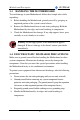
Motherboard Description 1-3 SY-7IWA-F HANDLING THE MOTHERBOARD To avoid damage to your Motherboard, follow these simple rules while unpacking: Ø Before handling the Motherboard, ground yourself by grasping an unpainted portion of the system's metal chassis. Ø Remove the Motherboard from its anti-static packaging. Hold the Ø Motherboard by the edges and avoid touching its components. Check the Motherboard for damage. If any chip appears loose, press carefully to seat it firmly in its socket.
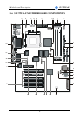
Motherboard Description SY-7IWA-F 1-5 SY-7IWA-F MOTHERBOARD LAYOUT JP1 PS/2 KB PS/2 Mouse Connector Connector JP11 1 1 1 USB 1 ATX Power CPUFAN 3 PWRFAN JP15 JP16 1 3 1 3 3 1 USB 2 Socket 370 PRT COM1 VGA Intel Fw82810 DC-100 1 FDC 3 COM2 1 SDRAM SDRAM 4 J10 CODEC AC97 1 WOL Header 4 Winbond W83627HF -AW J11 IR1 5 1 1 DIMM 3 1 DIMM 2 3 MIC JACK DIMM 1 JP44 LINE-IN JP2 J6 1 AMR Intel 82802AB PCI Slot #1 PCI Slot #2 4MB JP9 Intel 3 3V Lithium Battery 1
Motherboard Description SY-7IWA-F 1-6 SY-7IWA-F MOTHERBOARD COMPONENTS A B C D E F G H I J K AD L AC AB AA M Z R N O P Q Y R X W V 5 U T S
Motherboard Description A B C D E F G H I J K L M N O P Q R S T U V W X Y Z AA AB AC AD SY-7IWA-F COM1/ COM2 Connectors Power-On by Win 98 Hot Key of USB Keyboard Jumper CPU Cooling Fan Connector Power Cooling Fan Connector PGA370 Socket ATX Power Supply Connector CPU Core Voltage Adjust Jumpers Intel FW82810-DC100 GMCH (Graphic Memory Control Hub) Chip DIMM Bank Power – On by Keyboard Jumper Floppy Disk Drive (FDD) Port Bus Mastering E-IDE/ATAPI Ports CPU FSB Configuration Jumpers Intel 82802AB 4MB FWH
Motherboard Description SY-7IWA-F 1-7 CHIPSET To compliment the Intel ® Celeron processor, the Intel ® 810 chipsets delivers a balanced platform solution for value computing. The 810 chipset is a highly-integrated three-chip solution consisting of a Graphics & Memory Controller (Intel 82810), an I/O Controller (Intel82801), and a Firmware Hub (Intel 82802).
Motherboard Description SY-7IWA-F to AGP technology, resulting in a more responsive and cost-effective system. The 82810 Graphics Memory Controller Hub (GMCH) features Intel ® graphics technology and software drivers, using Direct AGP (integrated AGP) to create vivid 2D and 3D effects and images.
Motherboard Description SY-7IWA-F The Integrated Audio-Codec 97 controller enables software audio and modem by using the processor to run sound and modem software. By reusing existing system resources, this feature adds flexibility, and improves sound quality. The 82802 Firmware Hub (FWH) stores system BIOS and video BIOS, eliminating a redundant nonvolatile memory component. In addition, the 82802 contains a hardware Random Number Generator (RNG).
Motherboard Description Ø Ø Ø Ø Ø Ø Ø Ø Ø SY-7IWA-F efficient use of system memory for graphics, O/S and applications Optional 4MB of dedicated display cache video memory Enables SKU differentiation with increased 3D graphics performance improvement over Direct AGP Low-power sleep modes Energy Savings One software driver code base More stable platform, higher quality graphics, reduced OEM support costs Intel ® Random Number Generator (RNG) Enables ISV's to strengthen security products Digital Video Out p
Motherboard Description l l SY-7IWA-F Demultiplexing of address and data on the bus for near 100 percent bus efficiency AC timing for 133 MHz data transfer rates, allowing real data throughput in excess of 500 MB/sec 1-7.2 Universal Serial Bus (USB) The motherboard has two USB ports; one USB peripheral can be connected to each port. For more than two USB devices, an external hub can be connected to either port.
Motherboard Description SY-7IWA-F 1-7.3 IDE Support The motherboard has two independent bus-mastering PCI IDE interfaces. These interfaces support PIO Mode3, PIO Mode 4, ATAPI devices (e.g., CD-ROM), and Ultra DMA/33 synchronous-DMA mode transfers. The BIOS supports logical block addressing (LBA) and extended cylinder head sector (ECHS) translation modes. The BIOS automatically detects the IDE device transfer rate and translation mode.
Motherboard Description SY-7IWA-F 1-7.4 Real-Time Clock, CMOS SRAM, and Battery The real-time clock is compatible with DS1287 and MC146818 components. The clock provides a time-of-day clock and a multicentury calendar with alarm features and century rollover. The real-time clock supports 256 bytes of battery-backed CMOS SRAM in two banks that are reserved for BIOS use. The time, date, and CMOS values can be specified in the Setup program.
Motherboard Description l l l l SY-7IWA-F Compatible (standard mode) Bi-directional (PS/2 compatible) Bi-directional EPP. A driver from the peripheral manufacturer is required for operation. See Section 6.2 for EPP compatibility. Bi-directional high-speed ECP 1-8.3 Diskette Drive Controller The I/O controller is software compatible with the 82077 diskette drive controller and supports both PC-AT and PS/2 modes.
Motherboard Description SY-7IWA-F The keyboard controller also supports the hot-key sequence , software reset. This key sequence resets the computer’s software by jumping to the beginning of the BIOS code and running the Power On Self Test (POST). 1-8.5 Infrared Support The IR connection can be used to transfer files to or from portable devices like laptops, PDAs, and printers. 1-9 AUDIO SUBSYSTEM 1-9.
Motherboard Description SY-7IWA-F 1-11 WAKE ON LAN TECHNOLOGY Wake on LAN technology enables remote wakeup of the computer through a network. Wake on LAN technology requires a PCI add-in network interface card (NIC) with remote wakeup capabilities. The remote wakeup connector on the NIC must be connected to the onboard Wake on LAN technology connector. The NIC monitors network traffic at the MII interface; upon detecting a Magic Packet, the NIC asserts a wakeup signal that powers up the computer.
Hardware Installation SY-7IWA-F Chapter 2 HARDWARE INSTALLATION Congratulations on your purchase of SY-7IWA-F Motherboard. You are about to install and connect your new Motherboard. Note: Do not unpack the Motherboard from its protective antistatic packaging until you have made the following preparations. 2-1 PREPARATIONS Gather and prepare all the following hardware equipment to complete the installation successfully: 1. Slot 1 processor with built-in CPU cooling fan (boxed type).
Hardware Installation 2-2 SY-7IWA-F UNPACKING THE MOTHERBOARD When unpacking the Motherboard, check for the following items: u The SY-7IWA-F FW82810 AGP/PCI/AMR Motherboard u The Quick Start Guide u The Installation CD-ROM u SOYO 3-in-1 Bonus Pack CD-ROM (Norton AntiVirus, Ghost and Virtual Drive) u One IDE Device ATA 66 Flat Cable u One Floppy Disk Drive Flat Cable u Two Serial port flat cable with two 9-pin connectors bracket Warning: Do not unpack the Motherboard from its anti-static packaging unt
Hardware Installation SY-7IWA-F 2-3 INSTALLATION GUIDE We will now begin the installation of the Motherboard. Please follow the step-by-step procedure designed to lead you to a complete and correct installation. Warning: Turn off the power to the Motherboard, system chassis, and peripheral devices before performing any work on the Motherboard or system.
Hardware Installation SY-7IWA-F 2-3.1 CPU Installation To install the CPU, follow the steps below: Mark your CPU Frequency: Record the working frequency of your CPU that should be clearly marked on the CPU cover. 300MHz (66 x 4.5) 433MHz (66 x 6.5) 333MHz (66 x 5.0) 466MHz (66 x7..0) 366MHz (66 x 5.5) 500MHz (66 x7.5) 400MHz (66 x 6.0) This Motherboard is designed to be able to support processors with 100MHz FSB.
Hardware Installation SY-7IWA-F 3. Seat the processor in the socket completely and without forcing. 4. Then close the socket handle to secure the CPU in place. Remember to connect the CPU Cooling Fan to the appropriate power connector on the Motherboard. The fan is a key component that will ensure system stability. The fan prevents overheating, therefore prolonging the life of your CPU.
Hardware Installation SY-7IWA-F 2-3.2 SDRAM Memory Module Installation DIMM 3 DIMM 1 DIMM 2 Your board comes with three DIMM sockets, and supports up to 512MB main memory using industry standard Synchronous DRAM (SDRAM), single or double-sided, 3.3V unbuffered DIMM modules from 8MB to 256MB. Registered DIMMs or DIMMs populated with 4 bit wide SDRAM devices are not supported. PC100 compliant DIMM module is required regardless of 66 or 100MHz FSB speed.
Hardware Installation SY-7IWA-F Number of Memory Modules DIMM 1 DIMM 2 1 Double-sided/ Single-sided Double-sided/ Single-sided 2 Double-sided/ Single-sided Single-sided RAM Type Memory Module Size (MB) DIMM 3 Single-sided² SDRAM¹ 8/16/32/64/256 Mbytes Note: 1. PC100 Compliant DIMM module is required regardless of 66 or 100 MHz FSB speed. 2. If you want to use DIMM3, DIMM2 must be used as well to let the system work properly.
Hardware Installation SY-7IWA-F 2-3.3 Motherboard Connector 2-3.3.1 IDE Device Installation (HDD, CD-ROM) IDE 2 IDE 1 Pin -1 Secondary Primary IDE IDE This Motherboard offers two primary and secondary IDE device connectors (IDE1, IDE2). It can support up to four high-speed ATA 33/66 HDD or CD-ROM. Connect one side of the 40-pin flat cable to the IDE device (HDD or CDROM) and plug the other end to the primary (IDE1) or secondary (IDE2) directionally keyed IDE connector on the Motherboard.
Hardware Installation SY-7IWA-F 2-3.3.2 Floppy Drive Installation Pin -1 FDC Floppy Drive Connector The system supports 5 possible floppy drive types: 720 KB, 1.2 MB, 1.44 MB, 2.88 MB, and LS-120. In addition, this Motherboard supports a 3-mode (720KB/1.2MB/1.44MB) floppy commonly used in Japan. Connect one side of the 34-pin flat cable to the floppy drive and plug the other end to the floppy drive connector on the Motherboard. This Motherboard can support up to 2 floppy drives.
Hardware Installation SY-7IWA-F _ _ + HDD LED + Front Panel Connections _ ACPI LED + Speaker Key Lock 1 PWRBT _ + Power LED 1 Reset Plug the computer case's front panel devices to the corresponding headers on the Motherboard. 1. Power LED & KeyLock Plug the Power LED cable into the 5-pin Keylock header. Some systems may feature a KeyLock function with a front panel switch for enabling or disabling the keyboard. Connect the KeyLock switch to the 5-pin Keylock header on the Motherboard.
Hardware Installation SY-7IWA-F 2. Reset Plug the Reset push-button cable into the 2-pin Reset header on the Motherboard. Pushing the Reset button on the front panel will cause the system to restart the boot-up sequence. Reset Pin Assignment 1 Power Good GND 3. Speaker Attach the 4-pin PC speaker cable from the case to the Speaker header on the Motherboard. Speaker Pin Assignment _ + +5V Speaker out NC NC 4.
Hardware Installation SY-7IWA-F 5. IDE LED Attach the 2-pin IDE device LED cable to the corresponding IDE LED header on the Motherboard. This will cause the LED to lighten when an IDE (HDD, CD-ROM) device is active. HDD LED Pin Assignment + _ LED Anode LED Cathode 6. ATX Power On/Off Switch Attach the 2-pin momentary type switch to the PWRBT header for turning On or Off your ATX power supply.
Hardware Installation SY-7IWA-F 2-3.3.3 Back Panel Connections All external devices such as the PS/2 keyboard, PS/2 mouse, printer, modem, USB can be plugged directly onto the Motherboard back panel. Only after you have fixed and locked the Motherboard to the computer case you can start connecting the external peripheral devices. When connecting an external device, use the following figure to locate and identify which back panel connector to plug the device to.
Hardware Installation SY-7IWA-F PS/2 Mouse Connector Print Connector Joystick USB2 PS/2 Keyboard Connector USB1 VGA Connector Flat panel Connector LINE-OUT MIC LINE-IN 1. Parallel Port PRT This parallel port is used to connect the printer or other parallel devices. Plug the parallel device cable into the 25-pin female connector located at the rear panel of the Motherboard. Plug the keyboard jack directly into the 6-pin female PS/2 keyboard connector located at the rear panel of the Motherboard.
Hardware Installation SY-7IWA-F 3. Universal Serial Bus USB1/USB2 This Motherboard provides two USB ports for your additional devices. Plug the USB device jack into the available USB connector USB1 or USB2. Standard device drivers come with the Win98 for commonly used USB devices. - 4. With Win95, use the flow UHCI specifications. To use USB devices under Win95, usually you have to install the device driver comes with the USB device you have purchased.
Hardware Installation SY-7IWA-F 2-3.3.4 Other Connections 1. Serial Port COM 1 and COM2 The Motherboard package includes one set of serial port flat cables with 9pin connectors assembled on a bracket. Plug the 9-pin end of the flat cable into the COM1/COM2 serial port header on the Motherboard, as shown in the figure below, then fix the bracket connector to the rear panel of the computer case. Then plug your serial device cable directly into the 9-pin male connector located at the back of your computer.
Hardware Installation 2. SY-7IWA-F Wake-On-LAN (WOL) Attach the 3-pin connector from the LAN card which supports the WakeOn-LAN (WOL) function to the JP44 header on the Motherboard. This WOL function lets users wake up the connected computer through the LAN card.
Hardware Installation SY-7IWA-F 3. Infrared (IR1) Plug the 5-pin infrared device cable to the IR1 header. This will enable the infrared transfer function. This Motherboard meets both the ASKIR and HPSIR specifications. Please install according to the following pin assignment: Serial Infrared (IR1) Connector IR1 Pin Assignment 1 2 3 4 5 VCC IRRX GND IRTX 4. CD Line-in (J10,J11) This Motherboard provides two CD-Line in connectors.
Hardware Installation 5. SY-7IWA-F Cooling Fan Installation (1) CPU Cooling Fan After you have seated the CPU properly on the processor, attach the 3-pin fan cable to the CPUFAN connector on the Motherboard. The fan will stop when the system enters into Suspend Mode. (Suspend mode can be enabled from the BIOS Setup Utility, [POWER MANAGEMENT] menu.
Hardware Installation SY-7IWA-F (2) Chassis Cooling Fan Some chassis also feature a cooling fan. This Motherboard features a CHAFAN connector to provide 12V power to the chassis fan. Connect the cable from the chassis fan to the CHAFAN 3-pin connector. Install according to the following pin assignment: Chassis Cooling Fan CHAFAN Pin Assignment 1 GND 3 2 12V SENSOR (3) Power Cooling Fan Some power also feature a cooling fan.
Hardware Installation SY-7IWA-F 2-3.3.5 AGP VGA Card This motherboard comes with integrated AGP subsystem therefore, AGP VGA card is not needed. Other Display Cards: Insert other types of VGA cards into the PCI expansion slots according to card specifications. 2-3.3.6 ATX Power Supply Plug the connector from the power directly into the 20-pin male ATX PW connector on the Motherboard, as shown in the following figure.
Hardware Installation SY-7IWA-F Warning: Follow these precautions to preserve your Motherboard from any remnant currents when connecting to power supply: Turn off the power supply and unplug the power cord of the power supply before connecting to PW connector. This motherboard requires a power supply, that meets the ATX 2.03 specifications. Make sure the power supply can support at least 720mA on the 5V Standby lead.
Hardware Installation SY-7IWA-F 2-3.3.7 AMR (Audio Modem Riser) Connector This motherboard supports AMR (Audio-Modem Riser) slot that facilitates audio or modem riser card expansion. Since AC97 audio codec is built-in down on the motherboard, only “Secondary” mode modem riser (MR) card can be used on the AMR slot.
Hardware Installation SY-7IWA-F 2-3.4 Jumper Setting Step 1. Set J6 &JP2 to configure CPU FSB Frequency If the user wants to use the CPU at its standard FSB (Front Side Bus) Frequency, J6 has to be closed. This will make sure the system will provide the CPU with the FSB Frequency it was specified to run at. Make sure that JP2 is open when using this setting. If the user wants to run the CPU at another (higher) FSB frequency however, J6 has to be open. In this case use JP2 to set the FSB frequency.
Hardware Installation SY-7IWA-F Step 2. Set JP9 for FWH Boot Block Write-Protect Setting this jumper to open will prevent the boot block area of the FWH (FirmWare Hub) chip from being written data into such that it is writeprotected from unwanted or abnormal write activity. Note: In some rare cases, the boot block area will need to be flashed to complete the BIOS upgrade procedure. Setting JP9 to open will cause incomplete BIOS update in that case.
Hardware Installation SY-7IWA-F Step 4. Enable/Disable Power-On by Win 98 Hot Key of USB Keyboard (JP11) You can choose to enable the Power-On by Win 98 Hot Key of USB Keyboard function by shorting pin 1-2 on jumper JP1; otherwise, short pin 2-3 to disable this function. Power-On by Win 98 Hot Key of USB Keyboard JP11 Setting Enable Short pin 1-2 to enable the PowerOn by Win 98 Hot Key of USB Keyboard function.
Hardware Installation Step 5. SY-7IWA-F CPU Core Voltage Adjust (JP15, JP16) In case your CPU is running on a frequency higher then it is specified for, increasing its core voltage can enhance its stability. Over-clocking your CPU does however force your system to operate outside of its specifications, and therefore SOYO can not guarantee system stability. CPU Core Voltage Adjust Default Vcore 2.5% higher 5.0% higher 7.
Hardware Installation SY-7IWA-F 2-3.5 CMOS Clearing (JP5) After you have turned off your computer, clear the CMOS memory by momentarily shorting pins 2-3 on jumper JP5, for a few seconds. Then restore JP5 to the initial 1-2 jumper setting in order to recover and retain the default settings. Jumper JP5 can be easily identified by its white colored cap.
Hardware Installation SY-7IWA-F Repeat this operation until you get the following screen. 3.
Hardware Installation SY-7IWA-F Step 1. Select [STANDARD CMOS SETUP] Set [Date/Time] and [Floppy drive type], then set [Hard Disk Type] to “Auto”. Step 2. Select [Load Optimized Defaults] Select the “Load Optimized Defaults” menu and type “Y” at the prompt to load the BIOS optimal setup. Step 3.
Hardware Installation SY-7IWA-F 2-3.8 Troubleshooting at First Start l 1. 2. 3. 4. 5. 6. What should I do if the Motherboard refuses to start? Check that all DIMM memory modules are inserted completely. Sometimes a DIMM that is not inserted properly can cause boot problems. Check whether all Add-on cards have been inserted properly. Reinsert the Add-on cards to make sure that they make proper contact with the slots.
Hardware Installation 2. 3. 4. SY-7IWA-F for more than 4 seconds to shut down the system.) Press and hold down the key while turning on the system power. Keep holding down the key until you see the message of the CPU type and frequency shown on the screen. Press the key during the system diagnostic checks to enter the Award BIOS Setup program. Select [Save & Exit SETUP] and press to save the new configuration to the CMOS memory, and continue the boot sequence.
BIOS Setup Utility SY-7IWA-F Chapter 3 BIOS SETUP UTILITY This Motherboard's BIOS setup program uses the ROM PCI/ISA BIOS program from Award Software Inc. To enter the Award BIOS program's Main Menu: 1. Turn on or reboot the system. 2. After the diagnostic checks, press the [Del] key to enter the Award BIOS Setup Utility.
BIOS Setup Utility SY-7IWA-F Hot Keys: Function keys give you access to a group of commands throughout the BIOS utility. Function Command Description Gives the list of options available for each F1 General Help item. Previous Restore the old values. These are the values F5 Values that the user started the current session with. Load FailLoads all items with the most conservative F6 Safe Defaults values. Load F7 Optimized Loads all options with the optimize values.
BIOS Setup Utility SY-7IWA-F SAVE AND EXIT SETUP Select the [SAVE & EXIT SETUP] option from the Main Menu to save data to CMOS and exit the setup utility. This option saves all your changes and causes the system to reboot. R O M C M O S A W S T A N D A R D B IO S C M O S F E A T U R E S C H IP S E T P O W E R A R D P C I/IS A U T IL I T Y S O F T W A R E , IN C .
BIOS Setup Utility SY-7IWA-F 3-1 SOYO COMBO SETUP This Motherboard does not use any hardware jumpers to set the CPU frequency. Instead, CPU settings are software configurable with the BIOS [SOYO COMBO SETUP]. After the hardware installation is complete, turn the power switch on, then press the key during the system diagnostic checks to enter the Award BIOS Setup program. The CMOS SETUP UTILITY will display on screen.
BIOS Setup Utility SY-7IWA-F 3-1.1 Quick CPU Frequency Setup Quick CPU Setting Frequency Setup Description 105/35 MHz 114/38 MHz 120/40 MHz 124/41 MHz 133/33 MHz 133/44 MHz 140/35 MHz 150/37 MHz Note CPU Host/PCI Clock Default 66/33 MHz 70/35 MHz 75/37 MHz 83/41 MHz 90/30 MHz 95/31 MHz 100/33 MHz CPU Ratio After you have selected the host clock, choose the right multiplier for the CPU. Options are: [2, 2.5, 3., 3.5, 4, 4.5, 5, 5.5,6,6.5,7.0,7.5,8.0].
BIOS Setup Utility SY-7IWA-F 3-1.3 Memory Buffer Strength Setting SMAA [7:4] / 1x / 1x SMAB [7:4] 4x / 4x 4x / 3x 4x / 2x 4x / 1x 3x / 4x 3x / 3x 3x / 2x 3x / 1x Description Note Default 2x / 4x 2x / 3x 2x / 2x 2x / 1x 1x / 4x 1x / 3x 1x / 2x 1x / 1x This item sets the strength of the buffer that drives the address section of the memory bus. Change the setting only if you are an experienced user. 3-1.
BIOS Setup Utility 3-1.5 Others Optional Setting SY-7IWA-F Description Note POWER ON Password Function Enables you to wake-up the system by entering a password at the keyboard. Hot KEY You can wake-up the system by pressing the key combination of your choice (Ctrl-F1~F12). Mouse Left Enables waking up the system by pressing either the right or left Mouse Right mouse button. BUTTON-ONLY Disables the Wake-Up by Default Keyboard function.
BIOS Setup Utility SY-7IWA-F 3-2 STANDARD CMOS SETUP Select the [STANDARD CMOS SETUP] option from the Main Menu and press [Enter] key. CMOS Setup Utility – Copyright ( C ) 1984-1999 Award Software Standard CMOS Features Date (mm:dd:yy) Time (hh:mm:ss) Fri, Jan 1 1999 1 : 22 : 12 4 IDE Primary Master 4 IDE Primary Slave 4 IDE Secondary Master 4 IDE Secondary Slave Press Enter None Press Enter None Press Enter None Press Enter None Drive A Drive B Floppy 3 Mode Support 1.44M, 3.5 in.
BIOS Setup Utility SY-7IWA-F 3-2.2 Hard Disks Type & Mode Choose the type and mode for the hard disks that you have already installed. Primary Setting Description Note (Secondary) Master & Slave IDE HDD Auto- Press Enter Detection IDE Primary Slave (User Type) Auto Access Mode Auto User None To auto-detect the HDD’s size, head …on this channel BIOS detects hard disk type Default automatically. User defines the type of hard disk. BIOS detects hard disk mode automatically.
BIOS Setup Utility SY-7IWA-F 3-2.4 Others Optional Setting Description Note Video EGA/VGA CGA 40 CGA 80 MONO (Monochrome) Select the video mode. Halt On ALL Errors No Errors All, But Keyboard All, But Diskette All, But Disk/Key When the BIOS detects system Default errors, this function will stop the system. Select which type of error will cause the system halt.
BIOS Setup Utility SY-7IWA-F 3-3 ADVANCED BIOS FEATURES Select the [Advanced BIOS Features] option from the Main Menu and press [Enter] key.
BIOS Setup Utility SY-7IWA-F 3-3.1 Virus Warning Setting Disabled Anti - Virus Protection Enabled Description Note If set to enabled, the Paragon Anti-Virus. Function will scan Default your boot drive for boot virusses. If a boot virus is detected, the BIOS will display a warning message. 3-3.2 Cache Memory Options Setting Description Note CPU Internal Cache Disabled Enabled Enables the CPU's internal Default cache. External Cache Disabled Enabled Enables the external memory. 3-3.
BIOS Setup Utility SY-7IWA-F 3-3.5 Boot Up NumLock Status Setting Boot Up NumLock Status On Note Puts numeric keypad in Default NumLock mode at boot-up. Puts numeric keypad in arrow key mode at boot-up. Off 3-3.6 Gate A20 Options Setting Gate A20 Options Description Normal Fast Description Lets chipset control GateA20. A pin in the keyboard controller controls GateA20. 3-3.
BIOS Setup Utility SY-7IWA-F 3-3.8 Security Option Use this feature to prevent unauthorized system boot-up or use of BIOS Setup. The following table describes the security settings. Setting Description System Each time the system is booted, the Security Option password prompt appears. Setup If a password is set, the password prompt only appears when you attempt to enter the BIOS Setup program.
BIOS Setup Utility SY-7IWA-F 3-4 ADVANCED CHIPSET FEATURES Caution: Change these settings only if you are already familiar with the Chipset. The [Advanced Chipset Features] option changes the values of the chipset registers. These registers control the system options in the computer.
BIOS Setup Utility SY-7IWA-F 3-4.1 CHIPSET FEATURES SETUP CHIPSET Setting Description FEATURES SDRAM CAS Latency Time 2 3 Use the default setting SDRAM Cycle Time Tras/Trc 5/7 6/8 Use the default setting SDRAM RASto-CAS Delay 3 2 Use the default setting System BIOS Disabled Cacheable Enabled The ROM area F0000H-FFFFFH is cacheable. Video BIOS Cacheable Note Default Default Default Default Disabled Enabled The video BIOS C0000H-C7FFFH is Default cacheable.
BIOS Setup Utility SY-7IWA-F 3-4.2 ONBOARD DISPLAY CACHE SETUP ONBOARD Setting Description DISPLAY CACHE SETUP Note Initial Display Cache Disabled Enabled Disable or enable the onboard display cache. Default CAS# Latency 3 2 Select the local memory clock Default periods. Paging Mode Control Select the paging mode control. RAS-to-CAS Override Select the display cache clock periods control.
BIOS Setup Utility SY-7IWA-F 3-5 INTEGRATED PERIPHERALS Caution: Change these settings only if you are already familiar with the Chipset. The [INTEGRATED PERIPHERALS] option changes the values of the chipset registers. These registers control the system options in the computer. The following screen shows setup default settings.
BIOS Setup Utility SY-7IWA-F The following tables describe each field in the INTEGRATED PERIPHERALS Menu and provide instructions on how to configure the IDE controls, FDC controls, and the onboard serial and parallel ports. 3-5.
BIOS Setup Utility SY-7IWA-F 3-5.3 IDE HDD Block Mode Setting Note IDE HDD Block Mode Disabled Invokes multi-sector transfer instead of one all HDDs support this function. 3-5.4 FDC Controls Setting Onboard FDC Disabled Note floppy controller Use the on-board floppy Default Enabled 3-5.
BIOS Setup Utility SY-7IWA-F Onboard Serial Ports (Continued) Onboard Serial Setting Description Ports Note UR2 Duplex Mode Half Duplex Choose [Half] or [Duplex] to Default set UR2 in half duplex mode or full duplex mode respectively. Refer to your IR device specifications to select the suitable mode. Use IR Pins IR-Rx2Tx2 RxD2,TxD2 Depending on the capabilities Default of the receiving device, set this item to full or half duplex.
BIOS Setup Utility SY-7IWA-F 3-5.7 Others Optional Setting PWRON After PWR-Fail On Off Former-Sts Description Note The system will switch on when power comes back after a power failure. The system will remain off Default when power comes back after a power failure. The system will return to the state it was in before the power failure when power returns. (i.
BIOS Setup Utility SY-7IWA-F 3-6 POWER MANAGEMENT SETUP The [POWER MANAGEMENT SETUP] sets the system's power saving functions. CMOS Setup Utility – Copyright ( C ) 1984-1999 Award Software Power Management Setup ACPI Function ACPI Suspend Type Power Management Video Off Method Video Off In Suspend Suspend Type MODEM Use IRQ Suspend Mode HDD Power Down USB KB Wake-Up From S3 Cpu Thermal-Throttling Enabled S3 (STR) User Define DPMS Yes Stop Grant 3 Disabled Disabled Disabled 62.
BIOS Setup Utility SY-7IWA-F 3-6.1 Power Management Controls Power Setting Description Management Controls ACPI function Disabled Enabled ACPI Suspend S1 (POS) Type S3 (STR) Power Management User Define Min Saving Max Saving ACPI (Advanced Configuration Power Management Interface) Note Default The system will enter the STR (Suspend To Ram) state during Default suspend. Lets you define the HDD and Default system power down times.
BIOS Setup Utility SY-7IWA-F Power Management Controls (Continued) Power Setting Description Management Controls Note HDD Power Down Disabled 1-15Min When the set time has elapsed, BIOS sends a command to the HDD to power down. This turns off the HDD motor. USB KB Wake-UP From S3 Disabled In order to allow the system Default Enabled to wake up from the S3 suspend state through a USB keyboard, set this item to enabled. CPU Thermal- 87.5% Throttling 75.0% 62.5% 50.0% 37.5% 25.
BIOS Setup Utility SY-7IWA-F 3-7 PNP/PCI CONFIGURATION SETUP This option sets the Motherboard's PCI Slots.
BIOS Setup Utility SY-7IWA-F 3-7.1 PNP/PCI Configuration Controls PNP/PCI Setting Description Controls PnP OS Installed Yes No Note Set this field to [Yes] if you are running Windows 95, which is PnP compatible. If the OS you are running Default (If there is any does not support PnP doubt, set this configuration. field to [No]) Reset Configuration Data Disabled Retain PnP configuration Default data in BIOS. Enabled Reset PnP configuration data in BIOS.
BIOS Setup Utility SY-7IWA-F PNP/PCI Configuration Setup (Continued) PNP/PCI Setting Description Setup Note How to set the BIOS to release the IRQ to the PnP Interrupt pool: PnP / PCI configuration Integrated Peripherals IRQ 15: PCI / ISA PnP On-Chip Secondary PCI IDE: disabled IRQ 14: PCI / ISA PnP On-Chip Primary PCI IDE: disabled Interrupt 12 will be released by the PnP IRQ 12 IRQ 12: PCI / ISA PnP BIOS automatically if the PS/2 Mouse Port is not used.
BIOS Setup Utility SY-7IWA-F 3-8 PC HEALTH STATUS This option sets the Motherboard's PC Health Status. CMOS Setup Utility – Copyright ( C ) 1984-1999 Award Software PC Health Status CPU Warning Temperature Current System Temp. Current CPU Dio Temp. Current CPUFAN Speed Current CHSFAN Speed Current PWRFAN Speed Vcore VTT 3.3V + 5V +12V VBAT (V) 5VSB (V) áâàß:Move Enter:Select F5:Previous Values Disabled 25 º C / 77 º F 40 º C / 104 º F 5192 RPM 0 RPM 0 RPM 2.04 V 1.50 V 3.31 V 5.02 V 12.03 V 3.07 V 5.
BIOS Setup Utility SY-7IWA-F 3-8.1 CPU Device Monitoring CPU Device Setting Description Monitoring CPU Warning Temperature Disabled 50°C/122°F 53°C/127°F 56°C/132°F 60°C/140°F 63°C/145°F 66°C/150°F 70°C/158°F 75°C/167°F 80°C/176°F 85°C/185°F 90°C/194°F 95°C/203°F 100°C/212°F 110°C/230°F 120°C/248°F Default Set CPU temperature from 50°C to 70°C. The CPU will slow down when CPU temperature goes beyond the preset value.
BIOS Setup Utility SY-7IWA-F 3-9 LOAD OPTIMIZED DEFAULTS Select the [Load Optimized Defaults] option from the Main Menu to load the system values you have previously saved. This option is recommended if you need to reset the system setup and to retrieve the old values.
BIOS Setup Utility SY-7IWA-F 3-10 LOAD FAIL-SAFE DEFAULTS Select the [Load Fail-Safe Defaults] option from the Main Menu to load the system values you have previously saved. This option is recommended if you need to reset the system setup and to retrieve the old values.
BIOS Setup Utility SY-7IWA-F 3-11 SUPERVISOR PASSWORD Based on the setting you have made in the [Security Option] of the [BIOS FEATURES SETUP] section, the password prevents access to the system or the setup program by unauthorized users. Follow this procedure to set a new password or disable the password: 1. Choose [BIOS FEATURES SETUP] in the Main Menu and press [Enter]. Select the [Security Options] item and set the field to: a. [System]: The password is required every time the system is booted.
BIOS Setup Utility 3. SY-7IWA-F Enter your new password and press [Enter]. The following message appears, prompting to confirm the new password: Confirm Password: 4. Re-enter your password and then press [Enter] to exit to the Main Menu. This diagram outlines the password selection procedure: Press: ↔ entering the password Type Typethe thePassword Password and Press: Press: ↔ ROM PCI/ISA BIOS Press without CMOS SETUP UTILITYWithout entering password AWARD SOFTWARE, INC.
BIOS Setup Utility SY-7IWA-F 3-13 IDE HDD AUTO DETECTION This Main Menu function automatically detects the hard disk type and configures the [Standard CMOS Features] accordingly.
Drivers installation SY-7IWA-F Chapter 4 THE SOYO CD Your SY-7IWA-F Motherboard comes with a CD-ROM labeled "SOYO CD." The SOYO CD contains (1) the user's manual file for your new Motherboard, (2) the drivers software available for installation, and (3) a database in HTML format with information on SOYO Motherboards and other products. Step 1. Insert the SOYO CD into the CD-ROM drive The SOYO CD will auto-run, and the SOYO CD Start Up Menu will display as shown below.
Drivers installation SY-7IWA-F Step 2. Read SOYO [7IWA-F] Manual Click the Read Manual button to open the user's manual file of your Motherboard. Please note that if the Start Up program was unable to determine which SOYO Motherboard you own, the manual selection menu will pop up, as shown below. Then select the user's manual file that corresponds to your Motherboard model name and click OK. SOYO CD Manuals Please select your manual in the box below and click OK.
Drivers installation SY-7IWA-F However, to display the list of all drivers software available with SOYO Motherboards, click the Display all drivers on the SOYO CD button. Please make sure to install only the drivers adapted to your system, or otherwise this may cause system malfunctions. Driver Installation Please select the driver you want to install and click OK, You will have to restart your system after installation. Only the drivers that are relevant to your board are displayed initially.
Drivers installation SY-7IWA-F Ø INTEL Whitney security utility for Win 9x/NT This utility makes use of the random number generator in the FWH of your 810/820 chipset. for Win 95/98/NT. Ø 83627hf Winbond Hardware Doctor for Win 95/98 Your motherboard comes with a hardware monitoring IC. By installing this utility Temperature, Fan speed and Voltages can be monitored. It is also possible to set alarms when current system values exceed or fall below pre-set values.
Drivers installation SY-7IWA-F Step 5. Enter the SOYO CD Click the Enter SOYO CD button to enter the SOYO HTML database. The Start Up program will activate the default HTML browser installed on your system (for example, Internet Explorer or Netscape) to visualize the contents of the SOYO CD. The SOYO CD contains useful information about your Motherboard and other SOYO products available. For your convenience, this information is available in HTML format, similar to the format widely used on the Internet.
Crystal Audio Drivers installation SY-7IWA-F Chapter 5 CRYSTAL AUDIO DRIVER INSTALLATION Installing Crystal Audio drivers under Windows 95 The driver for Windows 95 can be installed through the SOYO-CD. To install it manually, go to the D:\driv_all\crystal\win95Drv directory and run setup.exe. The CD also contains a 16bit application for Windows 95, that can be installed through the SOYO-CD. To install it manually, go to the D:\driv_all\crystal\win95app directory and run setup.
Crystal Audio Drivers installation SY-7IWA-F 3. Delete Crystal INF in c:\windows\inf\other 4. Restart your PC for Plug and Play to reinitialize your system. Known Limitations 1. Clicking the Stop button causes loud pops while playing Midi through Media Player, when Headphone control is used. 2. Playing any wave using the Dsound application causes a loud pop when the Play button is clicked. 3. After Remove/Refresh, no software wavetable audio is available after a reboot. 4.
Crystal Audio Drivers installation SY-7IWA-F Installing Crystal Audio Drivers for Windows NT 1. Double click the MULTIMEDIA icon in the control panel. The Multimedia Properties windows will appear. Click on the Devices tab and press the Add button. 2. Select "Unlisted or Updated Drivers" from the list of drivers in the Add window by placing the mouse pointer over it and clicking the left mouse button. Press the OK button. 3.
SY-7IWA-F 92