SY-6IWM Motherboard **************************************************** Pentium ® III, Pentium ® II & Celeron Processor supported FW82810 AGP/PCI/AMR 66/100/133 MHz Front Side Bus supported Micro ATX Form Factor **************************************************** User's Manual
SOYO ™ SY-6IWM Copyright © 1999 by Soyo Computer Inc. Trademarks: Soyo is the registered trademark of Soyo Computer Inc. All trademarks are the properties of their owners. Product Rights: All names of the product and corporate mentioned in this publication are used for identification purposes only. The registered trademarks and copyrights belong to their respective companies. Copyright Notice: All rights reserved. This manual has been copyrighted by Soyo Computer Inc.
Table of Contents SY-6IWM Table of Contents CHAPTER 1 MOTHERBOARD DESCRIPTION ...............................................1 1-1 1-2 1-3 1-4 1-5 1-6 1-7 1-8 1-9 1-10 1-11 INTRODUCTION .....................................................................1 KEY FEATURES ......................................................................1 HANDLING THE MOTHERBOARD........................................3 ELECTROSTATIC DISCHARGE PRECAUTIONS ...................3 SY-6IWM MOTHERBOARD LAYOUT..................
Table of Contents SY-6IWM POWER MANAGEMENT SETUP...............................................................72 3-7 PNP/PCI CONFIGURATION SETUP......................................75 3-8 PC HEALTH STATUS.............................................................78 3-9 LOAD OPTIMIZED DEFAULTS ............................................80 3-10 LOAD FAIL-SAFE DEFAULTS ..............................................81 3-11 SUPERVISOR PASSWORD....................................................
Motherboard Description SY-6IWM Chapter 1 MOTHEBOARD DESCRIPTION 1-1 INTRODUCTION The SY-6IWM AGP/PCI/AMR Motherboard is a high-performance Slot 1 processor supported Micro ATX form-factor system board. SY-6IWM uses the FW82810 Chipset technology and supports Slot 1 processors. This Motherboard is fully compatible with industry standards and adds many technical enhancements.
Motherboard Description SY-6IWM Ø Supports onboard hardware monitoring and includes Hardware Doctor ™ utility Ø Fan speed control Ø Battery Low voltage Detect Ø Supports multiple-boot function Ø Y2K Complaint Ø Supports Audio Modem Riser slot (AMR 1.
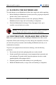
Motherboard Description SY-6IWM 1-3 HANDLING THE MOTHERBOARD To avoid damage to your Motherboard, follow these simple rules while unpacking: Ø Before handling the Motherboard, ground yourself by grasping an unpainted portion of the system's metal chassis. Ø Remove the Motherboard from its anti-static packaging. Hold the Motherboard by the edges and avoid touching its components. Ø Check the Motherboard for damage. If any chip appears loose, press carefully to seat it firmly in its socket.
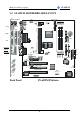
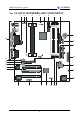
Motherboard Description SY-6IWM 1-5 SY-6IWM MOTHERBOARD LAYOUT JP1 PS/2 KB PS/2 Mouse Connector Connector ATX Power CPUFAN 3 1 1 USB 1 Slot 1 USB 2 PRT FDC Intel COM 1 3V Lithium Battery FW82810E 5 USB3 VGA 1 COM2 1 IDE 2 IDE 1 SDRAM SDRAM JOYSTICK AMR J10 AUX-IN 1 JP3JP2 3 JP7 PCI Slot #1 4 3 1 1 PCI Slot #2 4 PCI Slot #3 Back Panel 1 + PWRBT Power JP9 LED + Reset Intel 82802AB Intel 1 FW82801AA Winbond W83627HF -AW 1 4MB CODEC AC97 J9 CD-IN DIMM 3 1 4 D
Motherboard Description SY-6IWM 1-6 SY-6IWM MOTHERBOARD COMPONENTS A B C D E F H G I J AC K L M AB AA N Y X O ITE P W V U 5 T S R Q
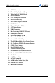
Motherboard Description SY-6IWM A COM 2 Connector B Power On by Keyboard Jumper C Wake-On-LAN( WOL) Header D Slot 1 Connector E CPU Cooling Fan Connector F Intel FW82810 Chip G ATX Power Supply Connector H DIMM Bank I Floppy Disk Drive (FDD) Port J 3V Lithium Battery K USB3 Connector L Bus Mastering E-IDE/ATAPI Ports M Front panel connectors N Intel 82802AB 4MB FWH O Chassis Cooling Fan Connector P Aureal 8810 Audio Chip Q The FWH Boot Block Write-Protect Jumper R Set Co
Motherboard Description SY-6IWM 1-7 CHIPSET To compliment the Intel ® Celeron processor, the Intel ® 810 chipsets delivers a balanced platform solution for value computing. The 810 chipset is a highlyintegrated three-chip solution consisting of a Graphics & Memory Controller (Intel 82810), an I/O Controller (Intel82801), and a Firmware Hub (Intel 82802).
Motherboard Description SY-6IWM The 82810 Graphics Memory Controller Hub (GMCH) features Intel ® graphics technology and software drivers, using Direct AGP (integrated AGP) to create vivid 2D and 3D effects and images. The 82810 chip features integrated Hardware Motion Compensation to improve soft DVD video quality and a digital video out port that enables connection to traditional TVs or the new space-saving digital flat panel displays. Intel ® Dynamic Video Memory Technology (D.V.M.T.
Motherboard Description SY-6IWM eliminating a redundant nonvolatile memory component. In addition, the 82802 contains a hardware Random Number Generator (RNG). The Intel® RNG provides truly random numbers to enable fundamental security building blocks supporting stronger encryption, digital signing, and security protocols.
Motherboard Description SY-6IWM security products Ø Digital Video Out port Allows connection of traditional TV or new digital flat panel displays; compatible with DVI specification Ø Soft DVD MPEG 2 playback with Hardware Motion Compensation Lifelike video and audio Ø 100-MHz System Bus capable Flexibility for performance headroom Ø 2 USB ports Plug and Play Ø Multiple Intel ® 810 chipset SKUs for Value PC price points Lower platform and manufacturing costs with single motherboard design Product
Motherboard Description SY-6IWM attached to the cable. Use shielded cable that meets the requirements for a fullspeed USB device.
Motherboard Description SY-6IWM 1-7.2 IDE Support The motherboard has two independent bus-mastering PCI IDE interfaces. These interfaces support PIO Mode3, PIO Mode 4, ATAPI devices (e.g., CD-ROM), and Ultra DMA/66 synchronous-DMA mode transfers. The BIOS supports logical block addressing (LBA) and extended cylinder head sector (ECHS) translation modes. The BIOS automatically detects the IDE device transfer rate and translation mode.
Motherboard Description SY-6IWM 1-7.3 Real-Time Clock, CMOS SRAM, and Battery The real-time clock is compatible with DS1287 and MC146818 components. The clock provides a time-of-day clock and a multicentury calendar with alarm features and century rollover. The real-time clock supports 256 bytes of battery-backed CMOS SRAM in two banks that are reserved for BIOS use. The time, date, and CMOS values can be specified in the Setup program.
Motherboard Description SY-6IWM operation. l Bi-directional high-speed ECP 1-8.3 Diskette Drive Controller The I/O controller is software compatible with the 82077 diskette drive controller and supports both PC-AT and PS/2 modes. In the Setup program, the diskette drive interface can be configured for the following diskette drive capacities and sizes. l 360 KB, 5.25-inch l 1.2 MB, 5.25-inch l 720 KB, 3.5-inch l 1.2 MB. 3.5-inch (driver required) l 1.25-1.44 MB, 3.5-inch l 2.88 MB, 3.
Motherboard Description SY-6IWM laptops, PDAs, and printers. 1-9 AUDIO SUBSYSTEM 1-9.1 Audio Connector The audio connectors include the following: l Back panel connectors: stereo line-level output (Line Out), stereo line-level input (Line In), and Mic In l CD Line - in (black) l Aux – in (natural/white) l Phone - in (green) 1-9.1.1CD Line - in Connector A1 x 4-pin ATAPI-style connector is available for connecting an internal CD-ROM drive to the audio mixer.
Motherboard Description SY-6IWM When suggested ratings for temperature, fan speed, or voltage are exceeded, an interrupt is activated. The hardware monitor component connects to the SMBus. 1-11 WAKE ON LAN TECHNOLOGY Wake on LAN technology enables remote wakeup of the computer through a network. Wake on LAN technology requires a PCI add-in network interface card (NIC) with remote wakeup capabilities. The remote wakeup connector on the NIC must be connected to the onboard Wake on LAN technology connector.
Hardware Installation SY-6IWM Chapter 2 HARDWARE INSTALLATION Congratulations on your purchase of SY-6IWM Motherboard. You are about to install and connect your new Motherboard. Note: Do not unpack the Motherboard from its protective anti-static packaging until you have made the following preparations. 2-1 PREPARATIONS Gather and prepare all the following hardware equipment to complete the installation successfully: 1. Slot 1 processor with built-in CPU cooling fan.
Hardware Installation 2-2 SY-6IWM UNPACKING THE MOTHERBOARD When unpacking the Motherboard, check for the following items: u The SY-6IWM FW82810 AGP/PCI/AMR Motherboard u This Quick Start Guide u The Installation CD-ROM u SOYO 3-in-1 Bonus Pack CD-ROM (Norton AntiVirus, Ghost and Virtual Drive) u The Foldable URM (Universal Retention Mechanism) Set (Factory installed on this motherboard) u One IDE Device ATA 66 Flat Cable u One Floppy Disk Drive Flat Cable u Serial port flat cable with a 9-pin connec
Hardware Installation SY-6IWM 2-3 INSTALLATION GUIDE We will now begin the installation of the Motherboard. Please follow the step-bystep procedure designed to lead you to a complete and correct installation. Warning: Turn off the power to the Motherboard, system chassis, and peripheral devices before performing any work on the Motherboard or system.
Hardware Installation SY-6IWM 2-3.1 CPU Installation Your SY-6IWM motherboard comes with a CPU retention set kit. The retention set is used to hold the processor attached to the Slot 1 CPU connector on the motherboard. Mark your CPU Frequency: Record the working frequency of your CPU that should be clearly marked on the CPU cover. FSB 66MHz 266MHz (66 x 4.0) 300MHz (66 x 4.5) 333MHz (66 x 5.0) 366MHz (66 x 5.5) 400MHz (66 x 6.0) 433MHz (66 x 6.5) 450MHz (100 x 4.5) 500MHz (100 x 5.0) 550MHz (100 x 5.
Hardware Installation SY-6IWM 1. Open the two sides by folding them up. 2. Push the locks on top of the CPU inward.
Hardware Installation 3. SY-6IWM Insert the CPU into the retention module. The CPU fits in the CPU slot in only ONE way, do not try to force it in. 4. After completely inserting the CPU, push the two locks on top of the CPU outward. Now your CPU is ready for use. To remove the CPU, press the two notches on top of the CPU inward. Now press the two slides on the retention module down and remove the CPU.
Hardware Installation SY-6IWM Note: Installing a heat sink and cooling fan on top of your CPU is necessary for proper heat dissipation. Failing to install these items may result in overheating and possible burn-out of your CPU. 2-3.1.1CPU Fan Installation Your Slot 1 processor kit comes with a cooling fan. Mount the fan on the processor according to the instructions provided by the manufacturer. The fan is a key component that will ensure system stability.
Hardware Installation SY-6IWM 2-3.2 SDRAM Memory Module Installation DIMM 3 DIMM 2 DIMM 1 ITE Your board comes with three DIMM sockets, and supports up to 512MB main memory using industry standard Synchronous DRAM (SDRAM), single or doublesided, 3.3V unbuffered DIMM modules from 8MB to 256MB. Registered DIMMs or DIMMs populated with 4 bit wide SDRAM devices are not supported. PC100 compliant DIMM module is required regardless of 66, 100 or 133 MHz FSB speed.
Hardware Installation SY-6IWM Number of Memory Modules DIMM 1 DIMM 2 1 Double-sided/ Single-sided Double-sided/ Single-sided 2 Double-sided/ Single-sided Single-sided RAM Type Memory Module Size (MB) DIMM 3 Single-sided² SDRAM¹ 8/16/32/64/256 Mbytes Note: 1. PC100 Compliant DIMM module is required regardless of 66, 100 or 133 MHz FSB speed. 2. If you want to use DIMM3, DIMM2 must be used as well to let the system work properly.
Hardware Installation SY-6IWM 2-3.3 Motherboard Connector 2-3.3.1IDE Device Installation (HDD, CD-ROM) IDE 2 ITE IDE 1 Pin -1 Secondary Primary IDE IDE This Motherboard offers two primary and secondary IDE device connectors (IDE1, IDE2.) It can support up to four high-speed HDD or CD-ROM. Connect one side of the 40-pin flat cable to the IDE device (HDD or CD-ROM) and plug the other end to the primary (IDE1) or secondary (IDE2) directionally keyed IDE connector on the Motherboard.
Hardware Installation SY-6IWM 2-3.3.2Floppy Drive Installation Pin -1 FDC Floppy Drive Connector ITE The system supports 5 possible floppy drive types: 720 KB, 1.2 MB, 1.44 MB, 2.88 MB, and LS-120. In addition, this Motherboard supports a 3-mode (720KB/1.2MB/1.44MB) floppy commonly used in Japan. Connect one side of the 34-pin flat cable to the floppy drive and plug the other end to the floppy drive connector on the Motherboard. This Motherboard can support up to 2 floppy drives.
Hardware Installation SY-6IWM _ _ + HDD LED + 2-3.3.3Front Panel Connections _ ACPI LED + Speaker Key Lock 1 PWRBT _ + Power LED 1 Reset ITE Plug the computer case's front panel devices to the corresponding headers on the Motherboard. 1. Power LED & KeyLock Plug the Power LED cable into the 5-pin Keylock header. Some systems may feature a KeyLock function with a front panel switch for enabling or disabling the keyboard.
Hardware Installation 2. SY-6IWM Reset Plug the Reset push-button cable into the 2-pin Reset header on the Motherboard. Pushing the Reset button on the front panel will cause the system to restart the boot-up sequence. Reset Pin Assignment 1 Power Good 3. GND Speaker Attach the 4-pin PC speaker cable from the case to the Speaker header on the Motherboard. Speaker Pin Assignment _ + +5V 4.
Hardware Installation 5. SY-6IWM IDE LED Attach the 2-pin IDE device LED cable to the corresponding IDE LED header on the Motherboard. This will cause the LED to lighten when an IDE (HDD, CDROM) device is active. HDD LED Pin Assignment + _ LED Anode LED Cathode 6. ATX Power On/Off Switch Attach the 2-pin momentary type switch to the PWRBT header for turning On or Off your ATX power supply.
Hardware Installation SY-6IWM 2-3.3.4Back Panel Connections All external devices such as the PS/2 keyboard, PS/2 mouse, printer, modem, USB can be plugged directly onto the Motherboard back panel. Only after you have fixed and locked the Motherboard to the computer case can you start connecting the external peripheral devices. When connecting an external device, use the following figure to locate and identify which back panel connector to plug the device to.
Hardware Installation SY-6IWM PS/2 Mouse Connector Printer Connector Joystick USB2 PS/2 Keyboard USB1 Connector 1. COM 1 Connector VGA Connector LINE-OUT MIC LINE-IN Parallel Port PRT This parallel port is used to connect the printer or other parallel devices. Plug the parallel device cable into the 25-pin female connector located at the rear panel of the Motherboard. Plug the keyboard jack directly into the 6-pin female PS/2 keyboard connector located at the rear panel of the Motherboard.
Hardware Installation 3. SY-6IWM Universal Serial Bus USB1/USB2 This Motherboard provides two USB ports for your additional devices. Plug the USB device jack into the available USB connector USB1 or USB2. - Standard device drivers come with the Win98 for commonly used USB devices. 4. With Win95, use the flow UHCI specifications. Onboard Serial Port COM1 External peripherals that use serial transmission scheme include: - serial mouse, - and modem.
Hardware Installation SY-6IWM 2-3.3.5Other Connections 1. Serial Port COM2 In addition to the onboard serial connector COM1 located at the rear panel, your Motherboard comes with a second serial port COM2 equipped with a flat cable and external connector. The Motherboard package includes one serial port flat cable with a 9-pin connector.
Hardware Installation 2. SY-6IWM Wake-On-LAN (WOL) Attach the 3-pin connector from the LAN card which supports the Wake-On-LAN (WOL) function to the JP44 header on the Motherboard. This WOL function lets users wake up the connected computer through the LAN card.
Hardware Installation 3. SY-6IWM Infrared (IR1) Plug the 5-pin infrared device cable to the IR1 header. This will enable the infrared transfer function. This Motherboard meets both the ASKIR and HPSIR specifications. Please install according to the following pin assignment: Serial Infrared (IR1) Connector IR1 Pin Assignment 1 2 3 4 5 VCC 4. IRRX GND IRTX CD Line-in (J9) This Motherboard provides two CD-Line in connectors. Please connect the 4-pin audio cable from your CD-ROM drive to either J9.
Hardware Installation 5. SY-6IWM Aux-in (J10) For Auxiliary Audio devices (1.0Vrms typ.). AUX-IN: J10 6. 4 Left 3 GND 2 GND 1 Right Phone-in (J11) Connect to modem sound connector.
Hardware Installation 7. SY-6IWM Cooling Fan Installation (1) CPU Cooling Fan After you have seated the CPU properly on the processor, attach the 3-pin fan cable to the CPUFAN connector on the Motherboard. The fan will stop when the system enters into Suspend Mode. (Suspend mode can be enabled from the BIOS Setup Utility, [Soyo Combo] menu.
Hardware Installation SY-6IWM (2) Chassis Cooling Fan Some chassis also feature a cooling fan. This Motherboard features a CHAFAN connector to provide 12V power to the chassis fan. Connect the cable from the chassis fan to the CHAFAN 3-pin connector. Install according to the following pin assignment: Chassis Cooling Fan CHAFAN Pin Assignment 1 GND 3 2 12V SENSOR Note: CPU cooling fan must be installed to prevent CPU from overheating and ensure system stability.
Hardware Installation SY-6IWM 2-3.3.6AGP VGA Card This motherboard comes with integrated AGP subsystem therefore, AGP VGA card is not needed. Other Display Cards: Insert other types of VGA cards into the PCI or ISA expansion slots according to card specifications. 2-3.3.7SFX/ATX Power Supply Plug the connector from the power directly into the 20-pin male SFX/ATX PW connector on the Motherboard, as shown in the following figure.
Hardware Installation SY-6IWM Warning: Follow these precautions to preserve your Motherboard from any remnant currents when connecting to power supply: Turn off the power supply and unplug the power cord of the power supply before connecting to PW connector. This motherboard requires a power supply, that meets the SFX 1.1 or ATX 2.03 specifications. Make sure the power supply can support at least 720mA on the 5V Standby lead. It you use the Wake-On-LAN (WOL) function.
Hardware Installation SY-6IWM 2-3.3.8AMR (Audio Modem Riser)Connector This motherboard supports AMR (Audio-Modem Riser) slot that facilitates audio or modem riser card expansion. If the user wants to use a Modem Riser (MR) card, make sure to use a Primary mode MR card.
Hardware Installation SY-6IWM 2-3.4 Jumper Setting Step 1. Enable/Disable Power-On by Keyboard (JP1) You may choose to enable the Power-On through Keyboard function by shorting pin 1-2 on jumper JP1; or short pin 2-3 to disable this function. Power-On by Keyboard JP1 Setting Enable Disable Short pin 1-2 to enable the PowerOn by Keyboard function. Short pin 2-3 and the Power-On by Keyboard function is disabled.
Hardware Installation SY-6IWM Your INTEL CPU has pins that tell the motherboard what frequency it is supposed to run at. If your CPU is a 66Mhz or a 100Mhz type, it will use pin B21 to indicate this. If it is high, the CPU is 66MHz type, if it is low, the CPU is a 100MHz type. If you have a 133MHz CPU, it will use an additional pin (A14) to tell the motherboard. If pin A14 is low, the CPU is a 133MHz type. For 66 and 100MHz CPUs this pin is high.
Hardware Installation Free Selection 66MHz JP3 open SY-6IWM JP7 100MHz open 1 2 Short Pin 12 1 2 Short Pin 12 open 1 2 133MHz open open 1 2 2-3.
Hardware Installation SY-6IWM 2-3.6 Power On You have now completed the hardware installation of your Motherboard successfully. 1. Turn the power on 2. To enter the BIOS Setup Utility, press the key while the system is performing the diagnostic checks, Note: If you have failed to enter the BIOS, wait until the boot up sequence is completed. Then push the RESET button and press key again at the beginning of boot-up, during diagnostic checks.
Hardware Installation SY-6IWM 2-3.7 Quick BIOS Setup This Motherboard does not use any hardware jumpers to set the CPU frequency. Instead, CPU settings are software configurable with the BIOS [Soyo Combo Feature]. The [Soyo Combo Feature] menu combines the main parameters that you need to configure, all in one menu, for a quick setup in BIOS.
Hardware Installation SY-6IWM Step 3. Select [Soyo Combo Feature] (a) CPU Host/PCI Clock CPU Frequency (MHz) 500MHz( 66 x 7.5) 750MHz (100 x 7.5) Manual 533MHz ( 66 x 8.0) 800MHz (100 x 8.0) 200MHz (66 x 3.0) 300MHz (100 x 3.0) 400MHz (133 x 3.0) 233MHz (66 x 3.5) 350MHz (100 x 3.5) 466MHz (133 x 3.5) 266MHz (66 x 4.0) 400MHz (100 x 4.0) 533MHz (133 x 4.0) 300MHz (66 x 4.5) 450MHz (100 x 4.5) 600MHz (133 x 4.5) 333MHz (66 x 5.0) 500MHz (100 x 5.0) 667MHz (133 x 5.0) 366MHz (66 x 5.
Hardware Installation SY-6IWM 2-3.8 Troubleshooting at First Start l What should I do if the Motherboard refuses to start? 1. Check that all DIMM memory modules are inserted completely. Sometimes a DIMM that is not inserted properly can cause boot problems. 2. Check whether all Add-on cards have been inserted properly. Re-insert the Add-on cards to make sure that they make proper contact with the slots. Try removing all Add-on cards one by one to see whether or not one of them is causing problems.
Hardware Installation SY-6IWM 2-3.9 Power Off There are two possible ways to turn off the system: 1. Use the Shutdown command in the Start Menu of Windows 95/98 to turn off your computer. 2. Press the mechanical power-button and hold down for over 4 seconds, to shutdown the computer. If you press the power-button for less than 4 seconds, then your system will enter into Suspend Mode. You are now ready to configure your system with the BIOS setup program.
BIOS Setup Utility SY-6IWM Chapter 3 BIOS SETUP UTILITY This Motherboard's BIOS setup program uses the ROM PCI/ISA BIOS program from Award Software Inc. To enter the Award BIOS program's Main Menu: 1. 2. Turn on or reboot the system. After the diagnostic checks, press the [Del] key to enter the Award BIOS Setup Utility.
BIOS Setup Utility SY-6IWM Hot Keys: Function keys give you access to a group of commands throughout the BIOS utility. Function F1 Command General Help Description Gives the list of options available for each item. Restore the old values. These are the values that Previous Values F5 the user started the current session with. Load Fail-Safe Loads all items with the most conservative F6 Defaults values. Load Optimized Loads all options with the optimize values.
BIOS Setup Utility SY-6IWM SAVE AND EXIT SETUP Select the [SAVE & EXIT SETUP] option from the Main Menu to save data to CMOS and exit the setup utility. This option saves all your changes and causes the system to reboot. R O M C M O S A W S T A N D A R D B IO S C M O S F E A T U R E S C H IP S E T P O W E R A R D P C I/IS A U T IL I T Y S O F T W A R E , IN C .
BIOS Setup Utility SY-6IWM 3-1 SOYO COMBO SETUP This Motherboard does not use any hardware jumpers to set the CPU frequency. Instead, CPU settings are software configurable with the BIOS [SOYO COMBO SETUP]. After the hardware installation is complete, turn the power switch on, then press the key during the system diagnostic checks to enter the Award BIOS Setup program. The CMOS SETUP UTILITY will display on screen.
BIOS Setup Utility SY-6IWM 3-1.1 Quick CPU Frequency Setup Quick CPU Setting Frequency Setup Description Note Select the host clock of your Slot 1 processor among these values. Note: For the 810 chipset, 66 and 100 MHz host clock frequencies are acceptable. However, the system stability is not guaranteed for other frequencies due to the limitations of this chipset.
BIOS Setup Utility SY-6IWM 3-1.4 Processor Number Feature Setting Setting Description Processor Number Feature Disabled Enabled Setting this item to enabled will allow application programs to read the ID-code in your Pentium III CPU, disabling this item will not allow any program to read the CPU ID code. 3-1.5 Quick Power On Self Test Setting Setting Description Quick Power On Self Test Disabled Enabled Provides a fast POTS at boot-up. 3-1.
BIOS Setup Utility 3-1.7 Others Optional Setting POWER ON Function SY-6IWM Description Note Password Enables you to wake-up the system by entering a password at the keyboard. Hot KEY You can wake-up the system by pressing the key combination of your choice (Ctrl-F1~F12). Mouse Left Enables waking up the system by pressing either the right or left Mouse Right mouse button. BUTTON-ONLY Disables the Wake-Up by Keyboard Default function.
BIOS Setup Utility SY-6IWM 3-2 STANDARD CMOS SETUP Select the [STANDARD CMOS SETUP] option from the Main Menu and press [Enter] key. CMOS Setup Utility – Copyright ( C ) 1984-1999 Award Software Standard CMOS Features Date (mm:dd:yy) Time (hh:mm:ss) Fri, Jan 1 1999 1 : 22 : 12 4 IDE Primary Master 4 IDE Primary Slave 4 IDE Secondary Master 4 IDE Secondary Slave Press Enter None Press Enter None Press Enter None Press Enter None Drive A Drive B Floppy 3 Mode Support 1.44M, 3.5 in.
BIOS Setup Utility SY-6IWM 3-2.2 Hard Disks Type & Mode Choose the type and mode for the hard disks that you have already installed. Primary Setting Description Note (Secondary) Master & Slave IDE HDD AutoDetection Press Enter To auto-detect the HDD’s size, head … on this channel IDE Primary Slave (User Type) Auto BIOS detects hard disk type automatically. User defines the type of hard disk. Default Access Mode Auto BIOS detects hard disk mode automatically.
BIOS Setup Utility SY-6IWM 3-2.4 Others Optional Setting Description Note Video EGA/VGA CGA 40 CGA 80 MONO (Monochrome) Select the video mode. Default Halt On ALL Errors No Errors All, But Keyboard All, But Diskette All, But Disk/Key When the BIOS detects system errors, this function will stop the system. Select which type of error will cause the system halt.
BIOS Setup Utility SY-6IWM 3-3 ADVANCED BIOS FEATURES Select the [Advanced BIOS Features] option from the Main Menu and press [Enter] key.
BIOS Setup Utility SY-6IWM 3-3.1 Virus Warning Setting Disabled Anti - Virus Protection Enabled Description Note If set to enabled, the Paragon AntiVirus. Function will scan your Default boot drive for boot virusses. If a boot virus is detected, the BIOS will display a warning message. 3-3.2 Cache Memory Options Setting Disabled CPU Internal Cache Enabled Disabled Enabled External Cache Description Enables the CPU's internal cache.
BIOS Setup Utility SY-6IWM 3-3.5 Boot Up NumLock Status Setting On Boot Up NumLock Status Off Description Puts numeric keypad in NumLock mode at boot-up. Puts numeric keypad in arrow key mode at boot-up. 3-3.6 Gate A20 Options Setting Gate A20 Options Normal Fast Description Lets chipset control GateA20. A pin in the keyboard controller controls GateA20. 3-3.
BIOS Setup Utility SY-6IWM 3-3.8 Security Option Use this feature to prevent unauthorized system boot-up or use of BIOS Setup. The following table describes the security settings. Setting Description System Each time the system is booted, the password Security Option prompt appears. Setup If a password is set, the password prompt only appears when you attempt to enter the BIOS Setup program.
BIOS Setup Utility SY-6IWM 3-4 ADVANCED CHIPSET FEATURES Caution: Change these settings only if you are already familiar with the Chipset. The [Advanced Chipset Features] option changes the values of the chipset registers. These registers control the system options in the computer.
BIOS Setup Utility SY-6IWM 3-4.
BIOS Setup Utility SY-6IWM 3-4.2 ONBOARD DISPLAY CACHE SETUP ONBOARD Setting Description DISPLAY CACHE SETUP Initial Display Cache Disabled Enabled CAS# Latency 3 2 Disable or enable the onboard display cache. Select the local memory clock periods. Paging Mode Control Select the paging mode control. RAS-to-CAS Override Select the display cache clock periods control.
BIOS Setup Utility SY-6IWM 3-5 INTEGRATED PERIPHERALS Caution: Change these settings only if you are already familiar with the Chipset. The [INTEGRATED PERIPHERALS] option changes the values of the chipset registers. These registers control the system options in the computer. The following screen shows setup default settings.
BIOS Setup Utility SY-6IWM 3-5.1 IDE Device Controls IDE Controls Setting Description Note Default On-Chip PCI IDE Ø Primary Ø Secondary Disabled Enabled Turn off the on-board IDE Use the on-board IDE IDE mode 0-4 0 is the slowest speed 4 is the fastest speed For better performance and Default stability, we suggest you use the Auto setting to set the HDD control timing.
BIOS Setup Utility SY-6IWM 3-5.4 FDC Controls FDC Controls Setting Description Onboard FDC controller Disabled Turn off the on-board floppy controller Use the on-board floppy controller Enabled 3-5.5 Onboard Serial Ports Onboard Serial Ports Setting Onboard Serial Port 1 / Serial Port 2 Disabled 3F8/IRQ4 2F8/IRQ3 3E8/IRQ4 2E8/IRQ3 Auto UART Mode Select Normal IrDA ASKIR Note Default Description Note Choose serial port 1 & 2's I/O address.
BIOS Setup Utility SY-6IWM 3 1 ECP Mode use DMA Choose DMA3 Choose DMA1 If [Parallel Port Mode] is set to [EPP] mode EPP 1.9 Select EPP port type 1.9 EPP Mode Select EPP 1.7 Select EPP port type 1.7 3-5.7 Others Optional Setting PWRON After PWR- On Fail Off Former-Sts Game Port Address Description Default Default Note The system will switch on when power comes back after a power failure. The system will remain off Default when power comes back after a power failure.
BIOS Setup Utility SY-6IWM 3-6 POWER MANAGEMENT SETUP The [POWER MANAGEMENT SETUP] sets the system's power saving functions.
BIOS Setup Utility SY-6IWM 3-6.1 Power Management Controls Power Setting Description Management Controls ACPI function Disabled Enabled ACPI Suspend Type S1 (POS) Power Management User Define S3 (STR) Note ACPI (Advanced Configuration Power Management Interface) The system will enter the STR (Suspend To Ram) state during suspend. Lets you define the HDD and system power down times.
BIOS Setup Utility SY-6IWM Power Management Controls (Continued) Power Setting Description Management Controls HDD Power Down Disabled 1-15Min CPU Thermal- 87.5% Throttling 75.0% 62.5% 50.0% 37.5% 25.0% When the set time has elapsed, BIOS sends a command to the HDD to power down. This turns off the HDD motor. Note Default Some older model HDDs may not support this advanced function. This item sets the proportion of the original clock frequency to which the CPU will slow do in Default suspend mode.
BIOS Setup Utility SY-6IWM 3-7 PNP/PCI CONFIGURATION SETUP This option sets the Motherboard's PCI Slots.
BIOS Setup Utility SY-6IWM 3-7.1 PNP/PCI Configuration Controls PNP/PCI Setting Description Controls PnP OS Installed Yes No Reset Configuration Data Disabled Enabled Note Set this field to [Yes] if you are running Windows 95, which is PnP compatible. If the OS you are running does Default not support PnP configuration. (If there is any doubt, set this field to [No]) Retain PnP configuration data Default in BIOS. Reset PnP configuration data in BIOS.
BIOS Setup Utility SY-6IWM PNP/PCI Configuration Setup (Continued) PNP/PCI Setup Setting Description Note Interrupt How to set the BIOS to release the IRQ to the PnP Interrupt pool: Line PnP / PCI configuration Integrated Peripherals IRQ 15 IRQ 15: PCI / ISA PnP On-Chip Secondary PCI IDE: disabled IRQ 14 IRQ 14: PCI / ISA PnP On-Chip Primary PCI IDE: disabled Interrupt 12 will be released by the PnP IRQ 12 IRQ 12: PCI / ISA PnP BIOS automatically if the PS/2 Mouse Port is not used.
BIOS Setup Utility SY-6IWM 3-8 PC HEALTH STATUS This option sets the Motherboard's PC Health Status. CMOS Setup Utility – Copyright ( C ) 1984-1999 Award Software PC Health Status CPU Warning Temperature Current System Temp. Current CPU Dio Temperature Current CPUFAN 1 Speed Current CPUFAN 2 Speed Vcore VTT 3.3V + 5V +12V VBAT (V) 5VSB (V) áâàß:Move Enter:Select F5:Previous Values Disabled 25 º C / 77 º F 40 º C / 104 º F 5192 RPM 0 RPM 2.04 V 1.50 V 3.31 V 5.02 V 12.03 V 3.07 V 5.
BIOS Setup Utility SY-6IWM 3-8.1 CPU Device Monitoring CPU Device Setting Description Monitoring CPU Warning Temperature Disabled 50°C/122°F 53°C/127°F 56°C/132°F 60°C/140°F 63°C/145°F 66°C/150°F 70°C/158°F 75°C/167°F 80°C/176°F 85°C/185°F 90°C/194°F 95°C/203°F 100°C/212°F 110°C/230°F 120°C/248°F Default Set CPU temperature from 50°C to 70°C. The CPU will slow down when CPU temperature goes beyond the preset value.
BIOS Setup Utility SY-6IWM 3-9 LOAD OPTIMIZED DEFAULTS Select the [Load Optimized Defaults] option from the Main Menu to load the system values you have previously saved. This option is recommended if you need to reset the system setup and to retrieve the old values.
BIOS Setup Utility SY-6IWM 3-10 LOAD FAIL-SAFE DEFAULTS Select the [Load Fail-Safe Defaults] option from the Main Menu to load the system values you have previously saved. This option is recommended if you need to reset the system setup and to retrieve the old values.
BIOS Setup Utility SY-6IWM 3-11 SUPERVISOR PASSWORD Based on the setting you have made in the [Security Option] of the [BIOS FEATURES SETUP] section, the password prevents access to the system or the setup program by unauthorized users. Follow this procedure to set a new password or disable the password: 1. Choose [BIOS FEATURES SETUP] in the Main Menu and press [Enter]. Select the [Security Options] item and set the field to: a. [System]: The password is required every time the system is booted.
BIOS Setup Utility 3. SY-6IWM Enter your new password and press [Enter]. The following message appears, prompting to confirm the new password: Confirm Password: 4. Re-enter your password and then press [Enter] to exit to the Main Menu. This diagram outlines the password selection procedure: Press: ↔ entering the password Type Typethe thePassword Password and Press: Press: ↔ ROM PCI/ISA BIOS Press without CMOS SETUP UTILITYWithout entering password AWARD SOFTWARE, INC.
BIOS Setup Utility SY-6IWM 3-13 IDE HDD AUTO DETECTION This Main Menu function automatically detects the hard disk type and configures the [Standard CMOS Features] accordingly.
Drivers installation SY-6IWM Chapter 4 THE SOYO CD Your SY-6IWM Motherboard comes with a CD-ROM labeled "SOYO CD." The SOYO CD contains (1) the user's manual file for your new Motherboard, (2) the drivers software available for installation, and (3) a database in HTML format with information on SOYO Motherboards and other products. Step 1. Insert the SOYO CD into the CD-ROM drive The SOYO CD will auto-run, and the SOYO CD Start Up Menu will be shown as below.
Drivers installation SY-6IWM Please note that if the Start Up program was unable to determine which SOYO Motherboard you own, the manual selection menu will pop up, as shown below. Then select the user's manual file that corresponds to your Motherboard model name and click OK. SOYO CD Manuals Please select your manual in the box below and click OK.
Drivers installation SY-6IWM sure to install only the drivers adapted to your system, or otherwise this cause system malfunctions. Driver Installation Please select the driver you want to install and click OK, You will have to restart your system after installation. Only the drivers that are relevant to your board are displayed initially. Intel Whitney VGA Drivers for Win 9x Intel .
Drivers installation Ø SY-6IWM Whitney Winbond hardware Doctor for Win 95/98 Your motherboard comes with a hardware monitoring IC. By installing this utility Temperature, Fan speed and Voltages can be monitored. It is also possible to set alarms when current system values exceed or fall below pre-set values. Select which driver you want to install and click OK, or click Cancel to abort the driver installation and return to the main menu.
Drivers installation SY-6IWM Note: If no HTML browser is installed on your system, the Start Up program will prompt you on whether or not you would like to install the Internet Explorer* browser. Click YES to install the HTML browser. After the installation is complete, please restart your system. Then re-run the SOYO CD and you will be able to browse the SOYO HTML database.
Aureal Audio Drivers installation SY-6IWM Chapter 5 AUREAL SOUND DRIVER INSTALLATION Installation of the Aureal Sound drivers under Windows 95/98 SYSTEM REQUIREMENTS: 1. Access to Microsoft Windows 95 or Microsoft Windows 98 installationCD-ROM. 2. Good-quality speakers or headphones and connecting cables. 3. Joystick and MIDI keyboard for testing the gameport. Wavetable Memory Requirements: The Vortex hardware wavetable engine uses a native 4MB sample set.
Aureal Audio Drivers installation SY-6IWM Installed drivers may include Vortex PCI audio, Vortex wavetable, Vortex mixer, and vortex Sound Blaster emulation. Depending on the version of Windows 95/98 and the configuration of the system, you may be prompted to provide several file locations. Here are the CD-ROMs and directory locations for which you may be prompted: Windows 95/98 Installation Disk \driv-all\Aureal\Win9x Vortex Application Setup \driv-all\Aureal\A3DDemos Windows NT 4.
SY-6IWM 92