SY-5EMA Super 7TM Mainboard ************************************************ Pentium ® Class CPU supported ETEQ82C663 PCI/AGP Mainboard ATX Form Factor ************************************************ User's Guide & Technical Reference
SOYO ™ SY-5EMA About This Guide This User's Guide is for assisting system manufacturers and end users in setting up and installing the mainboard. Information in this guide has been carefully checked for reliability; however, no guarantee is given as to the correctness of the contents. The information in this document is subject to change without notice. Copyright Notice Copyright 1998, Soyo Computer Inc. All rights reserved. This manual is copyrighted by Soyo Computer Inc.
Table of Contents SY-5EMA Table of Contents SY-5EMA MAINBOARD LAYOUT ....................................................... 1 CHAPTER 1 INTRODUCTION........................................................... 2 1-1 KEY FEATURES ............................................................ 2 1-2 HANDLING THE MAINBOARD...................................... 5 1-3 ELECTROSTATIC DISCHARGE PRECAUTIONS......... 5 CHAPTER 2 HARDWARE SETUP ....................................................
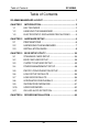
Mainboard Features SY-5EMA SY-5EMA Mainboard Layout 1 9 7 5 3 1 * USB2 JP4 USB1 12 10 8 6 4 2 CPUFAN JP3011 PS/2 Mouse Connector PS/2 KB Connector P.B. SRAM 64Kx64 ATX Power P.B.
Introduction SY-5EMA Chapter 1 INTRODUCTION The SY-5EMA AGP/PCI mainboard is a high-performance ATX form-factor system board. SY-5EMA uses the ETEQ82C663 PCI Chipset technology and supports Pentium ® class processors. This mainboard is fully compatible with industry standards and adds many technical enhancements.
Introduction u SY-5EMA System memory: 8MB to 640MB with EDO/SDRAM SY-5EMA PLATFORM FEATURES Board Size Socket 7 4-layer PCB, 19x30.5cm(7.
Introduction SY-5EMA HDD_LED PWRBT JP4 JP5 JP8 JP9, JP10 2-pin IDE Device LED Connector ATX Power On/Off Switch 2-pin Connector CPU Voltage Smart-Detect CMOS Clear Jumper CPU bus clock frequency Jumper SDRAM frequency Jumpers JP30 JP44 SW1 CPU Voltage Selection Jumper WOL (Wake-On-LAN) 3-pin Connector CPU frequency Settings Jumper BACK-PANEL FEATURES PRT 1 x Onboard 26-pin Female Parallel Printer Port COM1, COM2 2 x Onboard RS-232 Serial Port PS/2 KB 1 x Onboard PS/2 Keyboard Connector PS/2 Mouse USB1
Introduction SY-5EMA 1-2 HANDLING THE MAINBOARD To avoid damage to your mainboard, follow these simple rules while unpacking: Ø Before handling the mainboard, ground yourself by grasping an unpainted portion of the system's metal chassis. Ø Remove the mainboard from its anti-static packaging. Hold the Ø mainboard by the edges and avoid touching its components. Check the mainboard for damage. If any chip appears loose, press carefully to seat it firmly in its socket.
Hardware Setup SY-5EMA Chapter 2 HARDWARE SETUP Congratulations on your purchase of SY-5EMA Super 7 TM Mainboard. You are about to install and connect your new mainboard. Note: Do not unpack the mainboard from its protective anti-static packaging until you have made the following preparations. 2-1 Preparations Gather and prepare all the following hardware equipment to complete the installation successfully: 1. Pentium processor with CPU cooling fan. 2. DIMM memory module 3. 4. 5. 6. 7. 8. 9. 10.
Hardware Setup SY-5EMA 2-2 Unpacking the Mainboard When unpacking the mainboard, check for the following items: Ø The SY-5EMA ETEQ82C663 PCI/AGP Mainboard Ø This Quick Start Guide * Ø The Installation CD-ROM * Ø One IDE Device Flat Cable Ø One Floppy Disk Drive Flat Cable * If your board comes with a driver disc and a paper manual, the Quick Start Guide and the CD-ROM are not included in the package. Warning: Do not unpack the mainboard from its anti-static packaging until you are ready to install it.
Hardware Setup SY-5EMA 2-3 Installation Guide We will now begin the installation of the mainboard. Please follow the step-by-step procedure designed to lead you to a complete and correct installation. Step 1. CPU Installation Follow these instructions to install your Pentium ® class processor correctly. Locate the CPU socket labeled Socket 7 on your mainboard and note the distinctive pinhole arrangement. Note the corresponding pinhole arrangement on the processor.
Hardware Setup SY-5EMA Follow these steps to install the CPU in the Socket 7: 1. Lift the socket handle up to a vertical position. 2. Align the blunt edge of the CPU with the matching pinhole distinctive edge on the socket. 3. Seat the processor in the socket completely and without forcing. 4. Then close the socket handle to secure the CPU in place. 1 2 3 Step 2. 4 CPU Fan Installation Your Pentium ® processor kit comes with a cooling fan.
Hardware Setup Step 3. SY-5EMA CPU Voltage Setting (JP30 & JP4) * CPU Voltage JP4 CPU Voltage Smart-Detect Please verify the correct voltage with your dealer before installation. Use the following tables to set JP30 to the proper "Voltage Value", according to the specifications marked on your CPU: This mainboard comes with pre-configured setting of CPU voltage. However the voltage of your CPU maybe different with the default setting.
Hardware Setup SY-5EMA Note: For Dual voltage CPUs, JP4 must be set to enable. And at the same time make sure that the voltage setting of JP30 is correct. Incorrect setting may damage CPU. Those processors may come in various voltages on different markets. Therefore, always make sure you know the type of the CPU you are installing and adjust the settings on JP30 accordingly. This motherboard supports CPU voltages from 2.0 to 3.52V in 0.1V increments.
Hardware Setup SY-5EMA Voltage Settings for Various Processors Processor Voltage Value: JP30 Voltage Setting Intel P54C - P100 Intel P54C - P133 Intel P54C - P166 Intel P54C - P200 Intel P55C - P166 Intel P55C - P200 Intel P55C - P233 AMD K5 - PR100 AMD K5 - PR133 AMD K5 - PR166 AMD K6 166 AMD K6 200 AMD K6 233 AMD K6 266 AMD K6 300 AMD K6-2 266 AMD K6-2 300 AMD K6-2 333 AMD K6-2 350 12 10 8 6 4 2 11 9 7 5 3 1 12 10 8 6 4 2 11 9 7 5 3 1 VCORE:3.5V VI/O:3.5V 12 10 8 6 4 2 11 9 7 5 3 1 VCORE:2.
Hardware Setup SY-5EMA Voltage Settings for Various Processors (continued) Processor Voltage Value: JP30 Voltage Setting Cyrix 6x86(L) PR166+ The Cyrix 6x86(L) come in several versions Cyrix 6x86(L) PR200+ with different voltages. Please ask your dealer for the correct voltage. Cyrix 6x86MX-PR166* Cyrix 6x86MX-PR200* 11 12 Cyrix 6x86MX-PR233* 9 10 7 VCORE:2.9V 8 Cyrix 6x86MX-PR266* 5 6 3 VI/O:3.
Hardware Setup Step 4. SY-5EMA CPU Frequency Setting (SW1) * 6 5 4 3 2 1 SW1 Host Bus Frequency 6 5 4 3 2 1 SW1 Frequency Multiplier The SY-5EMA mainboard is designed to support most Pentium® class processors currently on the market. Jumpers SW1 is used to configure the mainboard frequency parameters to match the working frequency of your CPU.
Hardware Setup l SY-5EMA CPU FREQUENCY SETTING (SW1) Configure the SW1 jumpers to the settings that match your CPU speed. Refer to the following tables to set the Frequency Multiplier and Host Bus Frequency of your CPU: Frequency Multiplier Host Bus Frequency Multiplier 1 2 3 1.5/3.5x 2.0x* 2.5x 3.0x 4.0x 4.5x 5.
Hardware Setup SY-5EMA Please refer to the following table that gives you the correct frequency settings for the specific brand and model of CPU you are installing on this mainboard. Frequency Settings for Intel® Processors Processor Bus AGP PCI Frequency Ratio Frequency Setting Clock Clock Clock Setting: SW1 Intel P54C - P100 1.5 x 66MHz 66MHz 33MHz ON 1 2 3 4 5 6 Intel P54C - P133 2.0 x 66MHz 66MHz 33MHz ON 1 2 3 4 5 6 Intel P54C - P166 2.
Hardware Setup SY-5EMA Frequency Settings for AMD ™ Processors Processor Bus AGP Ratio Frequency Setting Clock Clock PCI Clock AMD K5 - PR100 33MHz 1.5 x 66MHz 66MHz Frequency Setting: SW1 ON 1 2 3 4 5 6 AMD K5 - PR133 2.0 x 66MHz 66MHz 33MHz ON 1 2 3 4 5 6 AMD K5 - PR166 2.5 x 66MHz 66MHz 33MHz ON 1 2 3 4 5 6 AMD K6 - 166 2.5 x 66MHz 66MHz 33MHz ON 1 2 3 4 5 6 AMD K6 - 200 3.0 x 66MHz 66MHz 33MHz ON 1 2 3 4 5 6 AMD K6 - 233 3.
Hardware Setup SY-5EMA Frequency Settings for Cyrix ™ Processors Processor Bus AGP PCI Ratio Frequency Setting Clock Clock Clock Cyrix 6x86 - PR166+ 2.0 x 66MHz 66MHz 33MHz Frequency Setting: SW1 ON 1 2 3 4 5 6 Cyrix 6x86 - PR200+ 2.0 x 75MHz 75MHz 37.5MHz ON 1 2 3 4 5 6 Cyrix MX - PR166** 2.0 x 66MHz 66MHz 33MHz ON 1 2 3 4 5 6 Cyrix MX - PR200** 2.5 x 66MHz 66MHz 33MHz ON 1 2 3 4 5 6 Cyrix MX - PR200** 2.0 x 75MHz 75MHz 37.5MHz ON 1 2 3 4 5 6 Cyrix MX - PR233** 2.
Hardware Setup SY-5EMA Frequency Settings for Cyrix ™ Processors (Continued) Processor Bus AGP PCI Frequency Ratio Frequency Setting Clock Clock Clock Setting: SW1 Cyrix M II - 350** 3.0 x 100MHz 66MHz 33MHz ON 1 2 3 4 5 6 ** Set the proper CPU frequency according to the marking on the CPU. Over specification is not guaranteed.
Hardware Setup SY-5EMA Step 5. Set JP8,JP9,JP10 for SDRAM frequency JP8 is used to indicate the frequency of the CPU bus clock to the ETEQ chipset. JP9 and JP10 are used to determine that the SDRAM is running at the frequency of the CPU bus clock or the AGP clock. CPU BUS AGP BUS Clock Clock 66MHz 66MHz 75MHz 75MHz 83MHz 55MHz 95MHz 63.4MHz 100MHz 66MHz 112MHz 75MHz 124MHz 82.
Hardware Setup SY-5EMA Step 6. DRAM Module Installation This mainboard supports two strips of 72-pin 5V FPM/EDO DRAM (SIMM) from 4 to 64 MB and two strips 168-pin 3.3V/5V Unbuffered DIMM modules from 8 to 256 MB. The mainboard requires SIMM modules of at least 70ns access time. * SIMM1 SIMM2 DIMM2 DIMM1 This mainboard supports both EDO and SDRAM types of memory modules. Note: (1) Do not install EDO type of DIMM modules if you already use SDRAM in any DIMM bank..
Hardware Setup SY-5EMA Your board comes with tow DIMM sockets and two SIMM sockets, providing support for up to 512MB of main memory using DIMM modules from 8MB to 256MB;SIMM modules from 4MB to 64MB. For 66MHz host bus CPUs use 12ns or faster DIMM modules; for 83MHz or faster host bus CPUs use 8ns modules.
Hardware Setup Step 9. SY-5EMA Front Panel Connections * + HDD LED _ Turbo LED Speaker Keylock + _ Power LED PWRBT Reset Plug the computer case's front panel devices to the corresponding connectors on the mainboard. 1. Power LED & KeyLock Plug the Power LED cable into the 5-pin Keylock connector. Some systems may feature a KeyLock function with a front panel switch for enabling or disabling the keyboard. Connect the KeyLock switch to the 5-pin Keylock connector on the mainboard.
Hardware Setup SY-5EMA 3. Speaker Attach the 4-pin PC speaker cable from the case to the Speaker connector on the mainboard. 4. Turbo LED Connecting the 2-pin Turbo LED cable to the corresponding Turbo LED connector will cause the LED to light whenever the system is in Turbo mode. The manufacturer has permanently set this mainboard in Turbo mode due to most hardware and software compliance to turbo mode. 5.
Hardware Setup SY-5EMA Step 10. Back Panel Connections All external devices such as the keyboard, printer, PS/2 mouse, modem, USB, can be plugged directly onto the mainboard back panel. Only after you have fixed and locked the mainboard to the computer case can you start connecting the external peripheral devices. When connecting an external device, use the following figure to locate and identify which back panel connector to plug the device to.
Hardware Setup SY-5EMA 1. Onboard Serial Port COM1,COM2 External peripherals that use serial transmission scheme include: - serial mouse, - and modem. Plug the serial device cables directly into the COM1or COM2 9-pin male connector located at the rear panel of the mainboard. 2. Parallel Port PRT This parallel port is used to connect the printer or other parallel devices. Plug the parallel device cable into the 26-pin female connector located at the rear panel of the mainboard. 3.
Hardware Setup SY-5EMA 1. Wake-On-LAN (WOL) Attach the 3-pin connector from the LAN card which supports the Wake-On-LAN (WOL) function to the JP44 connector on the mainboard. This WOL function lets users wake up the connected computer through the LAN card. Please install according to the following pin assignment: Wake-On-LAN JP44 Pin Assignment GND 5VSB MP_Wakeup 1 2 3 2. Infrared (IR) Plug the 5-pin infrared device cable to the IR connector. This will enable the infrared transfer function.
Hardware Setup SY-5EMA Step 11. CPU Cooling Fan Installation After you have seated the CPU cooling fan properly on the processor, attach the 3-pin fan cable to the CPUFAN connector on the mainboard. To avoid damage to the system, install according to the following pin assignment: CPU Cooling Fan CPUFAN Pin Assignment 3 1 2 12V NC GND Step 12.
Hardware Setup SY-5EMA Step 13. ATX Power Supply Plug the connector from the power directly into the 20-pin male ATX PW connector on the mainboard, as shown in the following figure. * ATX Power Warning: Follow these precautions to preserve your mainboard from any remnant currents when connecting to ATX power supply: Turn off the power supply and unplug the power cord of the ATX power supply before connecting to ATX PW connector.
Hardware Setup SY-5EMA Please install the ATX power according to the following pin assignment: ATX Power 12V 5VSB PW-0K 5V 5V -5V GND 5V GND 5V GND GND GND PS-ON GND 3.3V 3.3V GND -12V 3.3V Ø Pay special care to the directionality. Step 14. CPU Voltage Smart-Detect (JP4) This Mainboard automatically detects and adjusts the CPU voltage to the proper value for Intel P54C/P55C and Cyrix 6x86(L) CPUs.
Hardware Setup SY-5EMA Step 15. CMOS Clearing (JP5) After you have turned off your computer, clear the CMOS memory by momentarily shorting pins 2-3 on jumper JP5, for a few seconds. Then restore JP5 to the initial 1-2 jumper setting in order to recover and retain the default settings.
Hardware Setup SY-5EMA Step 17. CACHE CONFIGURATION This mainboard has a built-in 512KB(5EMA/5) or 1MB(5EMA) Level 2 Pipelined Burst cache onboard to improve the system performance. The cache size and RAM locations are specified as follows: Cache Size Cache RAM TAG RAM 512 KB 5EMA/5 64K x 64 on U2 64K x 64 on U2,U3 16K x 8 on U5 32K x 8 on U5 1 MB 5EMA Cacheable Range WT: 64 MB WB: 128MB WT: 256 MB WB: 128MB Step 18.
Hardware Setup SY-5EMA 3. The BIOS Setup screen appears: ROM PCI/ISA BIOS CMOS SETUP UTILITY AWARD SOFTWARE, INC.
BIOS Setup Utility SY-5EMA Chapter 3 BIOS SETUP UTILITY This mainboard's BIOS setup program uses the ROM PCI/ISA BIOS program from Award Software Inc. To enter the Award BIOS program's Main Menu: 1. Turn on or reboot the system. 2. After the diagnostic checks, press the [Del] key to enter the Award BIOS Setup Utility. ROM PCI/ISA BIOS CMOS SETUP UTILITY AWARD SOFTWARE, INC.
BIOS Setup Utility SY-5EMA Hot Keys: Function keys give you access to a group of commands throughout the BIOS utility. Function F1 Shift F2 F5 Command Description Help Gives the list of options available for each item. Color Change the color of the display window. Old values Restore the old values. These are the values that the user started the current session with. Loads all options with the BIOS Setup default values. Loads all options with the Power-On default values.
BIOS Setup Utility SY-5EMA 3-1 STANDARD CMOS SETUP Select the [STANDARD CMOS SETUP] option from the Main Menu and press [Enter] key. ROM PCI/ISA BIOS STANDARD CMOS SETUP AWARD SOFTWARE, INC. Date (mm:dd:yy) : Fri, May 29 1998 Time (hh:mm:ss) : 9 : 42 : 43 HARD DISKS Primary Master Primary Slave Secondary Master Secondary Slave TYPE : : : : SIZE AUTO None None None CYLS HEAD 0 0 0 0 0 0 0 0 Drive A : 1.44M, 3.5 in.
BIOS Setup Utility SY-5EMA 3-1.2 Hard Disks Type & Mode Choose the type and mode for the hard disks that you have already installed. Primary Setting Description (Secondary) Master & Slave Type Auto 1-47 User Mode Note BIOS detects hard disk type Default automatically. Selects standard hard disk type. User defines the type of hard disk. Auto BIOS detects hard disk mode Default automatically.
BIOS Setup Utility SY-5EMA 3-1.4 Video Select the video mode: EGA/VGA (Default), CGA 40, CGA 80, Mono (Monochrome). 3-1.5 Halt On When the BIOS detects system errors, this function will stop the system. Select which type of error will cause the system halt: All Errors (Default), No Errors, All But Diskette, All But Keyboard, All But Disk/Key.
BIOS Setup Utility SY-5EMA 3-2 BIOS FEATURES SETUP Select the [BIOS FEATURES SETUP] option from the Main Menu and press [Enter] key. ROM PCI/ISA BIOS BIOS FEATURES SETUP AWARD SOFTWARE, INC.
BIOS Setup Utility SY-5EMA 3-2.1 Virus Warning Setting Virus Warning Disabled Enabled Description Enable this option to protect the boot sectors and partition tables of your hard disk. Any attempt to write to them will the system to halt and display a warning message. 3-2.2 Cache Memory Options Setting Description CPU Internal Cache Disabled Enabled Enables the CPU's internal cache. External Cache Note Default Disabled Enabled Enables the external memory.
BIOS Setup Utility SY-5EMA 3-2.3 System Boot Control Settings System Boot Setting Description Control Settings Quick Power On Disabled Self Test Enabled Provides a fast POTS at Default boot-up.
BIOS Setup Utility SY-5EMA System Boot Control Settings (continued) System Boot Setting Description Control Settings Gate A20 Option Normal Fast Memory Parity Check/ ECC Check Note Allows RAM access Default above 1MB using the fast gate A20 line. Enabled This allows to perform a Default redundancy check on the parity bit in the data strings. This method is used for error detection when the parity is not found. Disabled 3-2.
BIOS Setup Utility SY-5EMA 3-2.5 Other Control Options Other Control Setting Description Options Security Option Setup System IDE Second Channel Control Disabled Enabled Use this feature to prevent Default Unauthorized system boot-up or use of BIOS Setup. “Setup”, If a password is set, the password prompt only appears if you attempt to enter the Setup program. Each time the system is booted the password prompt appears. Turn off the on-board IDE. Use a PS/2 mouse.
BIOS Setup Utility SY-5EMA Other Control Options (Continued) Other Control Setting Description Options Video or Adapter BIOS Shadow Note Disabled Enabled Default The BIOS is shadowed in a 16K segment if it is enabled and if it has BIOS present. These 16 segments can be shadowed from ROM to RAM. BIOS shadow copies BIOS code from slower ROM to faster RAM. BIOS can then execute from RAM.
BIOS Setup Utility SY-5EMA 3-3 CHIPSET FEATURES SETUP Caution: Change these settings only if you are already familiar with the Chipset. The [CHIPSET FEATURES SETUP] option changes the values of the chipset registers. These registers control the system options in the computer. ROM PCI/ISA BIOS CHIPSET FEATURES SETUP AWARD SOFTWARE, INC.
BIOS Setup Utility SY-5EMA CHIPSET FEATURES SETUP CHIPSET Setting Description FEATURES Bank 0/1 DRAM Timing Bank 2/3 DRAM Timing Bank 4/5 DRAM Timing FP/EDO 70ns Normal Medium Fast, Turbo DRAM Read Pipeline Disabled Enabled Cache Rd+CPU Wt Pipeline Disabled Enabled Linear Burst Disabled Enabled Video BIOS Cacheable Disabled Enabled System BIOS Cacheable Disabled Enabled Memory Hole 15Mb Addr. Disabled Use the default setting Note Default Choose DRAM Timing.
BIOS Setup Utility SY-5EMA CHIPSET FEATURES SETUP (Continued) CHIPSET Setting Description FEATURES AGP Aperture Size 64M 4-256M AGP-2X Mode Disabled Enabled OnChip USB USB Keyboard Support Disabled Enabled Disabled Enabled Spread Spectrum Disabled Modulated Enabled V AGP could use the DRAM as its video RAM. Choose the JDRAM size that you wish to allocate as video RAM.
BIOS Setup Utility SY-5EMA 3-4 POWER MANAGEMENT SETUP The [POWER MANAGEMENT SETUP] sets the system's power saving functions. ROM PCI/ISA BIOS POWER MANAGEMENT SETUP ACPI function Power Management PM Control by APM Video Off Option Video Off Method Modem Use IRQ Sof-Off by PWR-BTTN ** PM Timers ** HDD Power Down Doze Mode Suspend Mode ** PM Events ** VGA LPT & COM HDD & FDD DMA/ master Modem Ring Resume RTC Alarm Resume AWARD SOFTWARE, INC.
BIOS Setup Utility SY-5EMA 3-4.1 Power Management Controls Power Setting Description Management Controls ACPI function Disabled Enabled Power User Define Management Note Default Enabled if you use Windows 98 and want to use ACPI Lets you define the HDD and system power down times. Doze timer Standby timer Suspend timer PM Control by APM Min Saving Max Saving 40 Min 20 Sec 40 Min 20 Sec 40 Min 20 Sec Yes To use Advanced Power Default Management (APM) you must run [power.exe] under DOS V6.
BIOS Setup Utility 3-4.2 PM Timers PM Timers Setting HDD Power Down SY-5EMA Description Note Disable Default Some older 1-15Min When the set time has model HDDs elapsed, BIOS sends a command to the HDD to may not support power down. This turns off this advanced function. the HDD motor.
BIOS Setup Utility 3-4.3 PM Events PM Events Setting VGA ON SY-5EMA Description Enabled the power managemnet. OFF LPT & COM LPT/COM Note Default Enabled the power management timer. Default Enabled the power management timers when the event is detected on the Hard Disk Drive and Floppy Disk Drive device. Default COM LPT NONE HDD & FDD ON OFF DMA/master ON The system will not have SIM signal until the master is finished while the master is working.
BIOS Setup Utility SY-5EMA PM Events (Continued) PM Events Setting IRQ# Primary Description Note IRQ3(COM2), IRQ4(COM1), IRQ5(LPT2), IRQ6(Floppy Disk), IRQ7(LPT1), IRQ12(PS/2 mouse), IRQ13(Coprocessor), IRQ14(HardDsik) Secondary IRQ9(IRQ2 Redir), IRQ10( Reserved), IRQ11(Reserved) Disabled IRQ8 (RTC Alarm), IRQ15 (Reserved) 52
BIOS Setup Utility SY-5EMA 3-5 PNP/PCI CONFIGURATION SETUP This option sets the mainboard's PCI Slots.
BIOS Setup Utility SY-5EMA 3-5.1 PNP/PCI Configuration Controls PNP/PCI Setting Description Controls PNP OS Installed Yes NO Use the default setting Note Disabled Resources Manual BIOS does not manage PCI/ISA Controlled By PnP card IRQ assignment. Requires to assign IRQ-# and DMA-# to PCI or ISA PnP manually. IRQ-3,4,5,7,9,10,11,12,14,15 assigned to: _ DMA-0,1,3,5,6,7 assigned to: _ Auto The Plug-and-Play BIOS Recommended auto manages PCI/ISA PnP card IRQ assignment automatically.
BIOS Setup Utility SY-5EMA 3-5.2 PNP/PCI Configuration Setup PNP/PCI Setting Description Setup Note If [Resources Controlled By] is set to [Manual] IRQ-# and DMA-# assigned to: CPU to PCI write Buffer PCI/ISA PnP Choose IRQ-# and DMA-# assigned to PCI/ISA PnP card. Legacy ISA Choose IRQ-# and DMA-# assigned to Legacy ISA card.
BIOS Setup Utility SY-5EMA 3-6 LOAD SETUP DEFAULTS Select the [LOAD SETUP DEFAULTS] option from the Main Menu to load the system values you have previously saved. This option is recommended if you need to reset the system setup and to retrieve the old values. ROM PCI/ISA BIOS Type [Y] to use the Setup CMOS SETUP UTILITY AWARD SOFTWARE, INC.
BIOS Setup Utility SY-5EMA 3-8 INTEGRATED PERIPHERALS Caution: Change these settings only if you are already familiar with the Chipset. The [INTEGRATED PERIPHERALS] option changes the values of the chipset registers. These registers control the system options in the computer. The following screen shows default settings. ROM PCI/ISA BIOS INTEGRATED PERIPHERALS AWARD SOFTWARE, INC.
BIOS Setup Utility SY-5EMA 3-8.1 IDE Device Controls IDE Controls Setting Description Onchip IDE Primary Channel Disabled Enabled Use the On-board IDE Channel Default Onchip IDE Second Channel Disabled Enabled Turn off the On-board IDE Channel Default IDE Prefetch Mode Disabled Enabled Enable to enhance system performance. Note Default IDE HDD Block Mode Disabled Enabled Invokes multi-sector Default transfer instead of one sector per transfer. Not all HDDs support this function.
BIOS Setup Utility 3-8.2 FDC Controls FDC Controls Onboard FDC controller SY-5EMA Setting Description Disabled Turn off the on-board floppy controller Use the on-board floppy controller Enabled 3-8.3 Onboard Serial Ports Onboard Serial Setting Ports Onboard UART 1 Onboard UART 2 Description Disabled 3F8/IRQ4 2F8/IRQ3 3E8/IRQ4 2E8/IRQ3 Auto Onboard UART 2 Mode Standard HPSIR ASKIR 59 Note Default Note Choose serial port 1 & Default 2's I/O address.
BIOS Setup Utility SY-5EMA 3-8.4 Onboard Parallel Ports IR Pins Controls Setting IR Duplex mode Half Full Use IR Pins IR-RX2TX2 IR-RX TX Description Note Select the IR mode your IR module supports Default Default 3-8.5 Onboard Parallel Ports Onboard Parallel Setting Ports Description Onboard Parallel Port 378 Disabled 3BC 278 Choose the printer I/O Default address. Parallel Port Mode ECP + EPP Normal EPP ECP The mode depends on your external device Default that connects to this port.
BIOS Setup Utility 3-9 SY-5EMA SUPERVISOR PASSWORD Based on the setting you have made in the [Security Option] of the [BIOS FEATURES SETUP] section, the password prevents access to the system or the setup program by unauthorized users. Follow this procedure to set a new password or disable the password: 1. Choose [BIOS FEATURES SETUP] in the Main Menu and press [Enter]. Select the [Security Options] item and set the field to: a. [System]: The password is required every time the system is booted.
BIOS Setup Utility 3. SY-5EMA Enter your new password and press [Enter]. The following message appears, prompting to confirm the new password: Confirm Password: 4. Re-enter your password and then press [Enter] to exit to the Main Menu. This diagram outlines the password selection procedure: Press: ↔ entering the password Type Typethe thePassword Password and Press: Press: ↔ ROM PCI/ISA BIOS Press without CMOS SETUP UTILITYWithout entering password AWARD SOFTWARE, INC.
BIOS Setup Utility SY-5EMA 3-11 IDE HDD AUTO DETECTION This Main Menu function automatically detects the hard disk type and configures the STANDARD CMOS SETUP accordingly. ROM PCI/ISA BIOS CMOS SETUP UTILITY AWARD SOFTWARE, INC.
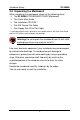
Drivers Installation SY-5EMA Chapter 4 DRIVERS INSTALLATION Your SY-5EMA Super 7 ™Mainboard comes with a CD-ROM labeled "SOYO CD." The SOYO CD contains the user's manual file for your new Mainboard, the drivers software available for installation, and a database in HTML format with information on SOYO Mainboards and other products. Step 1. Insert the SOYO CD into the CD-ROM drive The SOYO CD will auto-run, and the SOYO CD Start Up Menu will display as shown below.
Drivers Installation SY-5EMA Step 2. Installation procedure for Windows 95/98 The following describes the best way of installing Windows 95 or Windows 98 on your 5EMA mainboard: Ø The following BIOS default settings should not be changed: 1. The ‘USB Controller’item under ‘Chipset features’ is set to enabled. 2. The ‘USB Assigned IRQ’item under ‘PnP/PCI Configuration is set to enabled. You MUST have these two items enabled for Windows 95/98 to run properly on your system.
Drivers Installation SY-5EMA Select which driver you want to install and click OK, or click Cancel to return to the main menu. When the installation program of a driver starts running the SOYO CD will exit. After finishing the installation, restart the SOYO CD and install the next driver. Note: Once you have selected a driver, the system will automatically exit the SOYO CD to begin the driver installation program.