5XA5 82430 TX P54C/P55C PCI Mainboard User’s Guide & Technical Reference
SOYO TM About This Guide This User’s Guide is for assisting system manufacturers and end users in setting up and installing the mainboard. Information in this guide has been carefully checked for reliability; however, no guarantee is given as to the correctness of the contents. The information in this document is subject to change without notice. Copyright Notice C o p y r i g h t 1 9 9 7 , S o y o C o m p u t e r I n c . A l l r i g h t s r e se r v e d .
Table of Contents Chapter 1: Introduction .....................................................1 Key Features ................................................................................. 1 Unpacking the Mainboard ............................................................. 2 Electrostatic Discharge Precautions.............................................. 2 Mainboard Layout w/ Default Settings ......................................... 3 Chapter 2: Hardware Setup ......................................
IDE1/IDE2 - Onboard Primary/Secondary IDE HDD Connector…………………………………………………….18 IR1 - IR Connector ………….……….………………………18 Keylock & PW LED - Keylock and Power LED Connector...18 PS/2 KB Conn. - PS/2 Keyboard Connector…………….…..18 PS/2 Mouse Conn. - PS/2 Mouse Connector……….…….….19 PRT - Parallel Port Connector……………….…..……….….19 SPK - Speaker Connector…………………….….……….….19 USB1/USB1-Universal Serial Bus Connectors…….…….….19 JP44 - Wake-On-Lan (WOL) Header……..…..…....….….
1 Introduction The 82430 TX PCI mainboard is a high-performance ATX form-factor system board that supports P54C/P55C family CPUs. This mainboard is ful ly compa ti bl e wi th i nd us tr y sta nd ar ds , an d ad ds man y te ch ni ca l enhancements.
2 Introduction Unpacking the Mainboard The mainboard package contains: ¥ The 82430TX Mainboard ¥ This UserÕs Guide ¥ One IDE Bus Master driver diskette Note: Do not unpack the mainboard until you are ready to install it. Follow the precautions below while unpacking the mainboard. 1. Before handling the mainboard, ground yourself by grasping an unpainted portion of the systemÕs metal chassis. 2. Remove the mainboard from its anti-static packaging and place it on a grounded surface, component side up. 3.
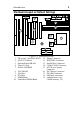
3 Introduction Mainboard Layout w/ Default Settings 14 5 4 14 18 13 15 17 16 9 10 8 7 2 1 6 2 19 3 11 12 1. 2. 3. 4. 5. 6. 7. 8. 9. 10. Figure 1Ð1. Mainboard Layout ZIF socket 7 (for P54C/P55C) 11. Floppy Connector 82430 TX Chipset 12. IDE1/IDE2 Connector Pipelined Burst SRAM 13. Parallel Port Connector Ultra I/O Chip 14. COM1/COM2 Connector PnP FLASH BIOS 15. ATX Power Supply Connector TAG SRAM 16. PS/2 Mouse Connector ISA Slots 17. PS/2 KB Connector PCI Slots 18.
4 Introduction Default settings are as follows: P54C/P55C 133MHz CPU, 512K Pipelined Burst cache , On - board PCI E - IDE Enabled , 2 high speed UARTS Enabled (w / 16550 FIFO), 1 EPP/ECP port (ECP + EPP mode),5V DRAM/3.3V DIMM, and ATX power supply. COM2 FLASH BIOS PRT 1 W83977F USB1 COM1 USB2 ATX PW Con.
2 Hardware Setup This chapter explains how to configure the mainboardÕs hardware. After you install the mainboard, you can set jumpers, install memory on the mainboard, and make case connections. Refer to this chapter whenever you upgrade or reconfigure your system. CAUTION: Turn off power to the mainboard, system chassis, and peripheral devices before performing any work on the mainboard or system.
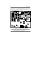
6 Hareware Setup JP2: Smart Detect CPU Voltage Function Auto/Manual Jumper This jumper is reserved for few old non-Intel CPUs which can not be detected correctly. If you run into problems while detecting the voltage of old non-Intel CPUs, remove this jumper to correct it. JP37: DIMM Voltage Select Jumper Most of DIMMs in the consumer market is still 3.3V and this jumper is reserved only for upgrading purpose in the near feature. If you have 5V SIMM or DIMM which matches the existing 3.
7 Hareware Setup CPU Type Configuration This section shows you how to configure your CPU step by step. Note that you need to check the CPU voltage before installation. This board supports the Intel P54C/P55C/MMX, Cyrix 6x86/6x86L/6x86MX, and AMD 5K86/K5/K6 CPUs. With the MMX technology supported, you should be able to use MMX CPUs and configure these CPUs as normal dual voltage CPUs. ❑ Step 1: Frequency Setting P54C/P55C – 75/90/100 CPU Settings (1.5 x clock) AMD K5 – PR75/PR90/PR100/PR120/PR133 (1.
Hardware Setup 8 P54C/P55C - 100/50 MHz P54C/P55C - 120/60 MHz Cyrix 6x86/6x86L - PR150+/60 MHz AMD K5/K6- PR150 82439TX Pentium - 133/66 MHz Cyrix 6x86/6x86L - PR166+/66 MHz Lithium Battery W25P240AF Cyrix 6x86/6x86L -PR200+/75MHz Figure 2-1-2. CPU Jumper Settings Note: 1. You must equip the CPU with a fan and heat sink for system stability. 2.
9 Hareware Setup P54C/P55C– 150/166 CPU Settings (2.5 x clock) Cyrix 6x86MX – PR166/PR200/PR233 CPU Settings (2.5 x clock) AMD K5/K6– PR166 CPU Setting P54C/P55C– 150/60 MHz Cyrix 6x86MX – PR166/60 MHz ON 123456 SW1 82439TX ON 1 2 3 4 5 6 P54C/P55C– 166/66 MHz Cyrix 6x86MX – PR200/66 MHz AMD K5/K6 – PR 166 SW1 ON 123456 Lithium Battery W25P240AF SW1 Cyrix 6x86MX – PR233/75 MHz ON 123456 SW1 Figure 2Ð1Ð3.
10 Hareware Setup P54C/P55C – 180/200 CPU Settings (3.0 x clock) Cyrix 6x86MX – PR233/PR266 CPU Settings (3.0 x clock) AMD K6 – PR200 CPU Setting P54C/P55C– 180/60 MHz ON 123456 SW1 82439TX ON 1 2 3 4 5 6 SW1 P54C/P55C– 200/66 MHz AMD-K6/PR2-200 Cyrix 6x86MX – PR233/66MHz ON 123456 Lithium Battery W25P240AF SW1 Cyrix 6x86MX – PR266/75 MHz ON 123456 SW1 Figure 2Ð1Ð4. CPU Jumper Settings Note: 1. You must equip the CPU with a fan and heat sink for system stability. 2.
11 Hareware Setup P54C/P55C – 233 CPU Settings (3.5 x clock) Cyrix 6x86MX – PR266 Cpu Setting (3.5 x clock) AMD K6 – PR233 CPU Setting ON 82439TX 123456 Socket 7 SW1 Lithium Battery (for 586 CPU Family) W25P240AF Figure 2Ð1Ð5. CPU Jumper Settings Note: The host bus frequency of Cyrix 6x86MXÐPR266 CPU is over the standard value, therefore, you need to use higher standard devices to meet the specifications of such CPUs, (i.e., high quality DRAM/VGA card.
12 Hareware Setup AMD K6 – PR266 CPU Setting (4.0 x clock) ON 82439TX 123456 Socket 7 SW1 (for 586 CPU Family) W25P240AF Lithium Battery Figure 2Ð1Ð6. CPU Jumper Settings AMD K6 – PR300 CPU Setting (4.5 x Clock) ON 82439TX 123456 Socket 7 SW1 Lithium Battery (for 586 CPU Family) W25P240AF Figure 2Ð1Ð7. CPU Jumper Settings Note: You must equip the CPU with a fan and heat sink for system stability.
13 Hareware Setup ❑ Step 2: CPU Single/Dual Voltage Setting There are two kinds of CPU input voltages due to various designs of CPUsÑsingle voltage and dual voltage. Set your CPU according to the type that you have. For Intel P54C/P55C single and dual voltage series CPUs, there is no need to adjust any jumper for CPU voltag due to the Smart Detect CPU Voltage function. Single Voltage CPU Setting Signal voltage CPUs use the same voltage for VIO and VCore and has been used traditionally.
14 Hareware Setup Dual Voltage CPU Setting Dual voltage CPUs are designed to use different voltage for VIO and VCore and they include Intel P55C series, Cyrix 6x86L/MX, AMD K6, and MMX technology included CPUs. Refer to the following figures to set these CPUsÕ voltage: 2.8V CPU (default) (i.e., P55C, 6x86L/MX) 11 9 7 5 3 1 Socket 7 (for 586 CPU Family) JP30 2.1V CPU (i.e., K6) 11 9 7 5 3 1 W25P240AF JP30 FDC IDE2 11 9 7 5 3 1 2.9V CPU (i.e., K6) 11 9 7 5 3 1 IDE1 JP30 JP30 3.2V CPU (i.e.
15 Hareware Setup Memory Configuration Table SIMM Bank DIMM Bank Bank 0 DIMM 1 RAM Type FPM/EDO Single RAM Module Size (MB) Note: 4/8/16/32/64 DIMM 2 DIMM 3 FPM/EDO SDRAM FPM/EDO/ SDRAM FPM/EDO/ SDRAM 8/16/32/64 8/16/32/64 8/16/32/64 Do not install FPM or EDO SIMM/DIMM when you already installed SDRAM type of DIMM. RAM Bank Installation Notice Due to the RAS line share architecture of TX chipset, do not install SIMM bank with DIMM3. All other combinations are acceptable.
16 Setup Hardware Multi I/O Port Addresses Default settings for multi I/O port addresses are shown in the table below. Port I/O Address IRQ Status LPT1* 378H 7 ECP + EPP COM1 3F8H 4 COM2 2F8H 3 * If default I/O port addresses conflict with other I/O card (e.g. sound cards or I/O cards), you must adjust one of the I/O addresses to avoid address conflict. (You can adjust these I/O addresses from the BIOS setup.
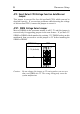
17 Hareware Setup JP43: CPU Cooling Fan Connector This 3-pins connector provides 12V power for the CPU cooling fan which matches the pin assignment of this connector. If you enable the Suspend Mode function in BIOS setup, this fan will stop when the system is into the suspend mode.
18 Hareware Setup RESET – Hardware Reset Control Attach the reset switch to RESET. Closing the RESETswitch restarts the system. HDD LED – HDD LED Connector Attach the cable of hard disk drive LEDs to this connector. The LED lights when an HDD is active. IDE1/IDE2 – On-board Primary/Secondary IDE HDD Connectors Attach cables of hard disk drives to these connectors. IR1 – IR Connector Attach a 5-pin infrared device cable to this connector for enabling the infrared transfer function.
19 Hareware Setup PS/2 Mouse Conn. – PS/2 Mouse Connector Attach 6-pin male PS/2 mouse cable to this connector to enable PS/2 mouse function. PRT – Parallel Port Connector Attach parallel port cable to this connector. SPK — Speaker Connector Attach a 4-pin case-mounted speaker to this connector. USB1/USB2 – Universal Serial Bus Connectors Attach USB device cable to these connectors for external USB device.
3 BIOS Setup The mainboardÕs BIOS setup program is the ROM PCI/ISA BIOS from Award Software Inc. Enter the Award BIOS programÕs Main Menu as follows: 1. 2. Turn on or reboot the system. After a series of diagnostic checks, you are asked to press DEL to enter Setup. Press the key to enter the Award BIOS program and the main screen appears: ROM PCI/ISA BIOS CMOS SETUP UTILITY AWARD SOFTWARE, INC.
21 BIOS Setup Standard CMOS Setup Run the Standard CMOS Setup as follows. 1. Choose ÒSTANDARD CMOS SETUPÓ from the Main Menu. A screen appears. ROM PCI/ISA BIOS STANDARD CMOS SETUP AWARD SOFTWARE, INC. Date (mm:dd:yy) : Fri, Feb 1 1995 Time (hh:mm:ss) : 7 : 30 : 33 HARD DISKS Primary Master Primary Slave Secondary Master Secondary Slave TYPE : : : : SIZE AUTO AUTO AUTO AUTO 0 0 0 0 Drive A : 1.44M, 3.5 in.
22 BIOS Setup Primary (Secondary) Master & Slave (Continued) Large Ð Drive A & B Choose 360KB , 5 1/4 in., 1.2MB , 5 1/4 in., 720KB , 3 1/2 in., 1.44M , 3 1/2 in.(default), 2.88 MB, 3 1/2 in. or Not installed Video Choose Monochrome, Color 40x25, VGA/EGA (default), Color 80x25 Halt On Choose halt mode when BIOS detects system errors: All Errors (default) All, But Diskette No Errors All, But Keyboard All, But Disk/Key 3.
23 BIOS Setup BIOS Features Setup Run the BIOS Features Setup as follows. 1. Choose ÒBIOS FEATURES SETUPÓ from the Main Menu and a screen with a list of items appears. (The screen below shows the BIOS default settings.) ROM PCI/ISA BIOS BIOS FEATURES SETUP AWARD SOFTWARE, INC.
24 BIOS Setup Boot Sequence Choose the boot device sequence as your need. For example, ÒA, C, SCSIÓ means BIOS will look for an operating system first from drive A, drive C, then SCSI device. Options of this function are: A, C, SCSI C, A, SCSI C, CDÐROM, A CDÐROM, C, A D, A, SCSI E, A, SCSI F, A, SCSI SCSI, A, C SCSI, C, A C only. Swap Floppy Drive Enabled changes the sequence of the drive A and drive B to drive B and drive A. (The Default setting is Disabled.
25 BIOS Setup PCI/VGA Palette Snoop Enabled: The color of the monitor may be incorrect if uses with MPEG card. Enable this option to make the monitor normal. Disabled: Disable Snoop function (default). OS Select for DRAM >64MB Video Adapter BIOS Shadow 3. OS2 Ð Choosing this when you are using OS/2 operation system. Non-OS/2 Ð Choosing this when you are using noOS/2 operation system. BIOS shadow copies BIOS code from slower ROM to faster RAM. BIOS can then execute from RAM.
26 BIOS Setup Chipset Features Setup The Chipset Features Setup option changes the values of the chipset registers. These registers control system options in the computer. Note: Change these settings only if you are familiar with the Chipset. Run the Chipset Features Setup as follows. 1. Choose ÒCHIPSET FEATURES SETUPÓ from the Main Menu and the following screen appears. (The screen below shows default settings.) ROM PCI/ISA BIOS CHIPSET FEATURES SETUP AWARD SOFTWARE, INC.
27 BIOS Setup DRAM Read Burst (EDO/FP) Use the default setting. DRAM Write Burst Timing Use the default setting. Fast EDO Lead Off Use the default setting. Refresh RAS# Assertion Use the default setting. Fast RAS to CAS Delay Use the default setting. DRAM Page Idle Timer Use the default setting. DRAM Enchanced Paging Use the default setting. Fast MA to RAS# Delay Use the default setting. SDRAM (CAS Lat/RAS-to-CAS) Use the default setting. SDRAM Speculative Read Use the default setting.
28 BIOS Setup Memory Hole At 15M16M 3. Choose Enabled or Disabled (default). Some interface cards will map their ROM address to this area. If this occurs, you should select Enabled, otherwise use Disabled. After you have finished with the Chipset Features Setup, press the key and follow the screen instructions to save or disregard your settings. Power Management Setup The Power Management Setup option sets the systemÕs power saving functions. Run the Power Management Setup as follows. 1.
29 BIOS Setup A short description of selected screen items follows: Power Management Options are as follows: User Define Ð LetÕs you define the HDD and system power down times (default). Disable Ð Disables the Green PC Features. Min Saving Ð Doze timer = 1 Hour Standby timer = 1 Hour Suspend timer = 1 Hour HDD Power Down = 15 Min Max Saving Ð Doze timer = 1 Min Standby timer = 1 Min Suspend timer = 1 Min HDD Power Down = 1 Min PM Control by APM Choose Yes or No (default).
30 BIOS Setup HDD Power Down When the set time has elapsed, the BIOS sends a command to the HDD to power down, which turns off the motor. Time is adjustable from 1 to 15 minutes. The default setting is Disabled. Some older model HDDs may not support this advanced function. VGA Active Monitor Choose Enabled (default) or Disabled. Enabled Ð enables the power management timers when a Òno activityÓ event is detected. Soft-Off by PORBTTN Choose Instant-off or Delay 4 Sec (default).
31 BIOS Setup Primary/Secondary IDE 0 Primary/Secondary IDE 1 Choose Enabled or Disabled (default). Enabled Ð Enables the power management timers when Òno activityÓ event is detected. Floppy Disk/ Serial Port/ Parallel Port Choose Enabled or Disabled. Enabled Ð enables the power management timers when Òno activityÓ event is detected. 3. After you have finished with the Power Management Setup, press the key to return to the Main Menu.
32 BIOS Setup A short description of screen items follows: Resources Manual Ð BIOS doesnÕt manage PCI/ISA PnP Controlled By card (i.e., IRQ) automatically. Auto Ð Reset Configuration Data BIOS auto manage PCI and ISA PnP card (recommended). Disabled Ð Retain PnP configuration data in BIOS. Enabled Ð Reset PnP configuration data in BIOS. IRQX and DMAX assigned to Choose PCI/ISA PnP or Legacy ISA.
33 BIOS Setup Load Setup Defaults This item loads the system values you have previously saved. Choose this item and the following message appears: ÒLoad SETUP Defaults (Y/N)? NÓ To use the SETUP defaults, change the prompt to ÒYÓ and press . This item is recommended if you need to reset the system setup. Note: The SETUP Defaults are optimized for the most stabilized performance.
34 BIOS Setup Integrated Peripherals The Integrated Peripherals option changes the values of the chipset registers. These registers control system options in the computer. Note: Change these settings only if you are familiar with the Chipset. Run the Integrated Peripherals as follows. 1. Choose ÒIntegrated PeripheralsÓ from the Main Menu and the following screen appears. (The screen below shows default settings:) ROM PCI/ISA BIOS INTEGRATED PERIPHERALS AWARD SOFTWARE, INC.
35 BIOS Setup IDE Primary Master UDMA/ IDE Primary Slave UDMA/ IDE Secondary Master UDMA/ IDE Secondary Slave UDMA Choose Auto (default) or Disabled. Auto Ð Supports Ultra DMA mode. On-chip Primary PCI IDE/ On-chip Secondary PCI IDE Enabled Ð Use the on-board IDE (default) Disabled Ð Turn off the on-board IDE USB Keyboard Support Choose Disabled (default) or Enabled. You need to use the regular keyboard to get in the BIOS Setup to enable this function before using the USB keyboard.
36 BIOS Setup IR Transmission Delay Choose Enabled (default) or Disabled. Due to the various design of IR devices, transmission delay has to be added on for different protocol. IR IRQ Select Choose IRQ3, IRQ4 (default), IRQ10, or IRQ11. If you have IRQ conflict problem during using the IR device, select another IRQ then try again. FIR Mode Use DMA Choose Disabled, 0, 1, or 3. When you choose FIR in IR Mode, you need to select a DMA channel to make the FIR transmission work.
37 BIOS Setup Supervisor Password Based on the setting you made in the ÒSecurity OptionÓ of the ÒBIOS FEATURES SETUPÓ, this Main Menu item lets you configure the system so that a password is required every time the system boots or an attempt is made to enter the Setup program. Change the password as follows: 1. Choose ÒSUPERVISOR PASSWORDÓ in the Main Menu and press . The following message appears: ÒEnter Password:Ó 2. Enter a password and press .
38 BIOS Setup User Password Based on the setting you made in the ÒSecurity OptionÓ of the ÒBIOS FEATURES SETUPÓ, this Main Menu item lets you configure the system so that a password is required every time the system boots or an attempt is made to enter the Setup program. Change the password as follows: 1. Choose ÒUSER PASSWORDÓ in the Main Menu and press . The following message appears: ÒEnter Password:Ó 2. Enter a password and press .
39 BIOS Setup IDE HDD Auto Detection This Main Menu item automatically detects the hard disk type and configures the STANDARD CMOS SETUP accordingly. Note: This function is only valid for IDE hard disks. ROM PCI/ISA BIOS CMOS SETUP UTILITY AWARD SOFTWARE, INC.
40 CPU Setting List Appendix : CPU Setting List Step 1 : Frequency Setting Processor Type Processor Bus Multiplier Clock AMD K5 50Mhz 1.5X PR75 AMD K5 60Mhz 1.5X PR90 AMD K5 66Mhz 1.5X PR100 AMD K5 60Mhz 1.5X PR120 AMD K5 66Mhz 1.5X PR133 AMD K5 60Mhz 2.0X PR150 AMD K5 66Mhz 2.5X PR166 AMD K6 66Mhz 2.5X PR166 AMD K6 66Mhz 3.0X PR200 AMD K6 66Mhz 3.5X PR233 AMD K6 66Mhz 4.0X PR266 AMD K6 66Mhz 4.5X PR300 Cyrix 6x86 60Mhz 2.0X P150+ Cyrix 6x86 66Mhz 2.
41 CPU Setting List Frequency Setting Continued Processor Cyrix 6x86 P200+ Cyrix MX P166 Cyrix MX P200 Cyrix MX P233 Cyrix MX P233 Cyrix MX P266 Cyrix MX P266 P54C P75 P54C P90 P54C P100 P54C P100 P54C P120 P54C P133 P54C/P55C P150 P54C/P55C P166 P54C/P55C P180 P54C/P55C P200 P55C P233 Bus Clock 75Mhz Multiplier 1-1 1-2 1-3 1-4 1-5 1-6 2.0X on off off on off off 60Mhz 2.5X on on 66Mhz 2.5X on on off off off off 75Mhz 2.
42 CPU Setting List Step 2 : Voltage Setting Voltage Single 3.3V 1-2 3-4 5-6 7-8 9-10 11-12 Possible CPUs on off off off on off Single 3.52V on off off off (Default) off on Dual 2.1V off off on off off off Dual 2.8V (Default) on off off off on off Dual 2.9V on off on off off off Dual 3.
Memory Configuration 43 Note for Memory Configuration On TX chipset motherboards, there is a memory limitation when the system has more than 2 DIMM sockets. The limitations are : 1. Maximum memory size is 256MB total for all RAM socket. 2. DIMM 1 won’t support 64MB or 128MB DIMMs with 64Mbit SDRAM cells. 3. If DIMM 2 and/or DIMM3 has 64MB or 128MB DIMM’s with 64Mbit SDRAM cells, DIMM 1 must be empty.
44 Appendix New Features In BIOS For easy management, some new features in ÒChipset Feature SetupÓ under the BIOS can help. Refer to the screen below for reference: ROM PCI/ISA BIOS CHIPSET FEATURES SETUP AWARD SOFTWARE, INC.