
Instruction Manual

P.O. BOX 2021 • SAN ANTONIO, TX • 78297 • 210-533-1231 • FAX: 210-533-2211
Revised 7/12
STANDARD FEATURES:
• Bottom door guide
• Door hanger
• Pneumatic emergency release
• Sloped-front cover box
• Hinged cover panel for maintenance access
• Vertical lock bar assembly
• ASTM F1643 Certified
Horizontal and Vertical Impact Test-Grade 1
• Prime paint finish
OPTIONAL FEATURES:
PILASTER RELEASE
-
(In lieu of pneumatic
release system.) Hip-high paracentric keyed
mechanical release mounted in a full-height
pilaster adjacent to the receiving jamb.
Specify “8010LP-1” keyed one side.
ELECTRIC KEYSWITCH
-
Paracentric or mogul
keyed local electric control switch
mounted below mechanical release mechanism in
pilaster.
Specify “8010LPK-1” for paracentric keyed
one side.
Specify “8010LPKM-1” for mogul keyed one side.
HOT DIP GALVANIZED FINISH - Available for
external applications with lift-off cover panel only.
Not available with standard hinged cover panel.
Specify [G] when ordering. Example: 8010LP-1G
NO LOCK OPEN - Specify “NLO.”
Door does not lock in open position.
FACTORY-WIRED CONTROL CABLE -
Specify “8010LWC.”
NOTE: Cover box minimum length =
(7"
overtravel) + (2 x clear opening) + 9".
*For doors exceeding 300 lbs. and/or greater
than 3’-2” clear opening, contact factory.
8010L PNEUMATIC
LOCKING SYSTEM
C8
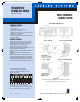
DETAIL A – SLOPED BOX
8010L PNEUMATIC SLIDING DOOR SYSTEM
DETAIL B – VERTICAL LOCK JAMB BAR
DETAIL D – BOTTOM DOOR GUIDE SECTION
DETAIL C – RECEIVER
RECEIVER JAMB SECTION
Flush receiver jamb allows frame
opening and clear opening to
be the same.
8010L Shown
Note: Other system configurations and details are available.
Call Customer Service for more information.
L O C K I N G S Y S T E M S
FOR GROUPS OF
SLIDING CELL DOORS
Maximum
security.
COVER BOX SECTION
7-1/2” deep x 1’-0-3/4” tall cover box
field welded 1” on 6” top and bottom
090604SouthernFolger_final:INSIDE 8/21/09 5:22 PM Page 44