
User Manual


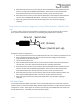


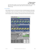
Table Of Contents
- Welcome
- Overview
- Connecting the Pedal
- Connections
- Reverb Engines
- Delay Engines
- Controls
- Hardware Shortcuts
- Preset Storage and Recall
- Universal Bypass
- Stereo Operation & Signal Routing
- External Control
- Neuro Desktop and Mobile Editors
- The Neuro Desktop Editor
- Downloading and Connecting the Neuro Desktop Editor
- Neuro Desktop Editor User Interface
- Connections
- Hardware Options
- Delay Controls (Engine A)
- Reverb Controls (Engine B)
- Routing Options
- Tap Tempo
- This section allows you to manually enter a tempo for your Delay repeats. You may type in a BPM (beats per minute) or ms (milli-seconds) numerically or use your cursor to “tap” the button at your desired tempo. Also in this section is the option to Sy...
- External Control
- Presets
- Device Tab
- Cloud Tab
- The Neuro Mobile App
- Neuro Hub
- MIDI
- USB
- Specifications
- Troubleshooting
- Frequently Asked Questions
- What kind of instruments can I connect to the Collider’s inputs?
- Can I power the Collider directly over USB, without using the 9 Volt supply?
- When connecting the Collider to a recording interface or mixer, should I used a Lo-Z (microphone) or Hi-Z (line / instrument) input?
- Why doesn’t the Collider respond to MIDI messages being sent to it?
- Can I use the Collider in my amp’s effects loop?
- How do I update the firmware?
- Rubber Feet
- Waste Disposal Notes
- Warranty
- Version History

SA263 Collider Delay+Reverb Owner’s Manual
33
5. Move the knobs you wish to control with the expression pedal to the minimum desired
position and then click the DELAY/TAP footswitch. The CONTROL LED will now blink even
faster (about 4 blinks per second). Note that you may control one or more knobs with the
expression pedal, up to three total knobs.
6. Move the knobs you wish to control with the expression pedal to the maximum desired
position and then click the DELAY/TAP footswitch. The CONTROL LED will now be lit solid red.
7. After setting the minimum and maximum knob positions, the parameter mapping is
complete.
Note: The parameter range can be inverted by swapping the minimum and maximum position of the
knobs during steps 5 and 6.
Note: To cancel a control assignment, press the CONTROL INPUT button at any time during the
process above.
Once a mapping is created, it can be stored as part of a user preset. This way, each preset can be
configured to have its own custom mapping.
External Control can be toggled on/off at any time by pressing the CONTROL INPUT button.
External Switch Used As Expression Input (Expression “Toggle”)
An external switch can also work as a sort of expression pedal that only has two positions: on and off.
The external switch can be either momentary or latching.
External Switch as Expression Toggle (1/4” TRS Connection – PEDAL IN Jack)
To use this mode, connect an external switch to PEDAL IN and set the PEDAL IN switch to the EXP
position instead of the SWITCH position. The following plug configuration is required:
Follow these steps for configuration:
1. Press the CONTROL INPUT button to enable external control. The CONTROL LED should be lit red.
2. Press and hold the CONTROL INPUT button until the CONTROL LED begins to blink slowly
(approximately one blink per second).
3. Tap the external switch once.
4. Click the DELAY/TAP footswitch once. The CONTROL LED will blink faster (about 2 blinks per
second). Now, it is time to map the external switch to the effect parameters.
Ground Power (Switch pull-up)
Switch Out
1/ 4”