SOUNDSTREAl’vl@ - SA80 SA 164 Power Amplifiers OWNERS MANUAL AND INSTALLATION GUIDE SOUNDSTREAM’ T E C H N O L O G I E S
CONGRA TULA TIONS! You now own a Soundstream Amplifier, the result of a unique design and engineering philosophy. To maximize the performance of your system, we recommend that you thoroughly acquaint yourself with its capabilities and features. Please retain this manual and your sales and installation receipts for future reference.
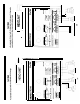
Key to Callouts 1. +12V - Connected to fuse or circuit breaker, then battery’s positive post. 0 2. Ground - Main ground connection. Bolt to a clean chassis ground in the vehicle. 3. Remote - Remote turn-on input from the head unit. Accepts +12V. 4. LED - Indicates amplifier power on. 5. Speaker Outpot Connections - Channels 1 & 2 6. Input Level - Variable from IOOmV to 23. 7. Inputs - Right and left channel inputs; only right channel input used in “Mono” mode. 6.
SA.164 v to Callouts I 1. - 2. / I i HANDCRAFTED IN U.S.A. 3. 4. 5. 6. 7. Top View (partial) 67 8 9 10 6. 9. 10. 11. Side View 12. 13. 14. 15. .f-Y i /\ / 15 ii’ CHANNELS \ 1&2 MAIN FUSE LOW PAS m FULL RANGE .14 I- 1 i Underside View 6 +I 2V - Connected to fuse or circuit breaker, then battery’s positive post. Ground - Main ground connection. Bolt to a clean chassis ground in the vehicle. Remote - Remote turn-on input from the head unit. Accepts +12V.
4 INSTALLATION STEP 1 b DESIGN FEATURES Handcrafted in the U.S.A. with mii-spec glass epoxy circuit boards, lowloss connections, gold-plated input connectors, and metal film resistors. SETTING THE CROSSOVER MODES Darlington High Current Discrete Output Topology - Soundstream’s “overbuilding” of the output section incorporates Darlington output devices sandwiched between the circuit board and the heatsink in a design called ChassisinkTM to ensure cool, efficient amplifier operation.
q INSTALLATION STEP 2 t 4 INSTALLATION STEP 3 b SELECTING INPUT MODES WIRING POWER AND GROUND The SA*164 can be driven with either one or two pairs of stereo inputs. If your source unit has front and rear outputs, you can take advantage of its fading capability by driving the multi-channel amplifiers with two pairs of input. When operating your Soundstream amplifier in mono, only one input is necessary. On Soundstream amplifiers, pairs of channels may be bridged for mono operation.
4 INSTALLATION STEP 4 t (Continued from page 7 1) INSTALLATION AND MOUNTING INTERNAL The Soundstream amplifiers are fused internally with automotive-type fuses. The fuses are accessible via a plastic plug on the bottom of the amplifier. Never replace the fuses with a higher value than what is supplied. This may result in amplifier damage and will void the warranty! REMOT; TURN-ON Connect the “Remote” to the turn-on lead from the source unit. When +12 volts is received, the amplifier will turn on.
l T~GTALLATI~~I STEP 5 t I I LEVEL SETTING ,-,, ~HEAD UNIT k The input levels are adjusted by means of the input level controls located on the front of the amplifier. In the ideal situation, all components in the audio system reach maximum undistorted output at the same time. The reason is because an amplifier will only make what comes into it bigger. So, if you send it a distorted signal from the head unit, it is going to amplify distorted information.
+ ,i. 2 W I .
SERVICE PROTECTION ClRCUITRY Your Soundstream amplifier is protected by a limited warranty. Please read the Your SA amplifier is protected against both overheating and short circuits by means of the following circuits: l Main power supply fuses. l Speaker output circuit breakers. l A fail-safe thermal protection circuit activating at 95°C. enclosed warranty card. SPECIFICA TIONS .
PARALLEUSERlES WIRING DIAGRAMS Amplifier I . ,,,” 4 Ohm ‘~,., /’ 4 Ohm’\, two 4 ohm woofers in series = 8 ohms two 4 ohm woofers in parallel = 2 ohms SOUNDSTREAk/‘@ T E C H N 0 L 0 G I SOUNDSTREAM TECHNOLOGIES 120 Blue Ravine Road . Folsom . California 95630 USA ph 916.351.1288 fax 916.351.0414 “er.