
Owner's Manual


WIRING DIAGRAM / GAIN SETTING
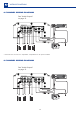
2 CHANNEL WIRING DIAGRAM
MODEL
BRIDGE / POWER
STEREO / POWER
STEREO OUTPUT VOLTAGE BRIDGE OUTPUT VOLTAGE
2Ω/ 600W1 / 300WΩ
17.3 V
34.6 V
1200.4
* Check the minimum speaker impedance at specs table
GND
13
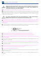
GAIN SETTING
Necessary equipament:
Digital AC voltmeter;
Media with sine wave test tone 60Hz
recorded at 0db;
Screwdriver 1/8" ( for gain set)
Set up procedure
This procedure is the same for both
gain controls;
Turn the gain control all the way down.
Disconnect the output cables from the
amplifier outputs;
Turn off
all processing (bass, treble,
loudness, EQ, etc.);
Set the source unit volume to 3/4 of
full volume.
Set the source unit's fader control to
center position;
Set the crossover selector switch in "F"
Use a 60Hz sine wave
Connect the AC voltmeter to the
speaker output connectors of the
amplifier. Make sure you test the voltage
at the correct connectors (+ and –);
Increase the gain control until the
target voltage is observed with the
voltmeter (see the chart below);
Once you have adjusted the amplifier
to its correct voltage output, turn off the
source unit and reconnect the speaker(s)
Download the tracks for set up in
https://soundigitalusa.com/tracks-for-set-
up/
4Ω/ 600W2 / 300WΩ
24.5 V
49.0 V
1200.4
2Ω
4Ω