OPTIMIZER parametric equalizer Owner´s Manual Operation . Applications . Measurements .
OPTIMIZER Owner´s Manual: Operation, Applications, Measurements, Specifications Written by Paul White and Hermann Gier Manual version 1.1/94 The information in this document has been carefully checked and is assumed to be correct. However Sound Performance Laboratory (SPL electronics GmbH) reserves the right to modify the product described in this manual at any time.
CONTENTS INTRODUCTION 4 INSTALLATION 7 CONNECTORS 7 OPERATING LEVEL 8 POWER SUPPLY 8 REAR PANEL 9 INPUT & OUTPUT SPECIFICATIONS APPLICATIONS 9 10 MASTERING WITH THE OPTIMIZER 10 OPTIMIZER USED IN THE INSERTS 11 CONTROLS 12 FRONT PANEL 12 DUAL 13 ACTIVE 13 MASTER-EQ 13 PEAK 13 BOOST/CUT (+/-) 14 BANDWIDTH Q 15 FREQUENCY & FREQUENCY RANGE 16 OUTPUT 18 NOTCH 19 PARAMETRIC, HIGHPASS, BANDPASS, LOWPASS 20 PHASE MEASUREMENTS 22 NOISE MEASUREMENTS 24 COMMON MODE REJE
INTRODUCTION Congratulations on purchasing the Optimizer, one of the most advanced and musical sounding parametric equalizer currently available. The Optimizer is a highly specialized and creative equali- The OPTIMIZER is designed for both corrective and creative applications, producing effects impossible to achieve using conventional EQ. Yet it remains very simple to operate. zer.
INTRODUCTION changing the filter settings. When broadening the bandwidth, the boost or cut will be reduced proportionally, so that the subjectively perceived loudness remains constant. The proportional-Q principle operates according to the way our hearing system perceives sound. With constant-Q equalizers there is often only a limited range of useable settings. Sometimes this is so narrow, you may wonder why the Q-control was not permanently fixed at the point it sounds really good.
INTRODUCTION addition each filter is equipped with a notch-filter. Selecting The depth of the Notch is in excess of 60dB the Notch mode overrides the mode switch selector. So complex combinations of filter types can be used in the same signal path. For example, a parametric filter could be combined with a High- and Low-pass and Notch filter.
tion as each filter is added to the signal path. The Optimizer overcomes this fault by using controllable all active output INSTALLATION stages resulting in a significantly improved phase response, even when all four filters are linked up. The Output control allows level adjustments to compensate for level changes due to dramatic boost or cut adjustments. The Optimizer is designed for standard 19” rack mounting and occupies 2U of rack space.
INSTALLATION POWER SUPPLY ce is not driving Optimizer´s filters sufficiently with the proviso that the Peak LED on the front panel is not continually flashing. This will achieve equalization at a lower signal level and will result in a more intensely processed sound. Note: this level change also effects the signal when the filters are in bypass, so you will loose direct comparability as the listening level changes. A Ground Lift switch is provided to assist in the elimination of ground loop problems.
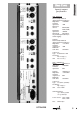
INSTALLATION REAR PANEL Input- & output specifications XLR - balanced: Inputs: Electronically balanced (differential) transformerless Impedance: = 20kOhms Nominal input level: +6dB Input level selector: HIGH (0dB) LOW(-10dB) Maximum input level: +22dBm Input peak: LED indicates potential peak 3dB before actual clipping.
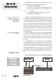
SET-UP & APPLCATIONS PARAMETRIC SET-UP: To use the Optimizer as a dualchannel, parametric equalizer proceed as follows: • Set all filters to PARAMETRIC • Set to DUAL mode and ensure MASTER BYPASS is out. • Use filter ACTIVE control to set up one equalizer sec- tion For precise location of the frequency you want, set the Boost/Cut control fully clockwise to provide maximum boost. at a time. • Select appropriate frequency range for each filter. • Set Q initially to midway point.
at treating stereo programme material - either at the mixing stage or during post-production. The special characteristics of the Optimizer allow you to add weight and punch to the bass end of a mix or to lift harmonic detail out of the top The Optimizer can produce results as dramatic as subbass synths or harmonic generators, but without side effects. end of a mix, without inadvertently adding harshness or muddiness to the sound.
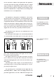
CONTROLS Start positions: Peak-LED illuminates 3dB before clipping FRONT PANEL Boost/cut (+/-)/ Roll-off (0) Bandwidth (1) The OPTIMIZER is equipped with four filter bands which can be used either in a 4-band mono or dual 2-band stereo configuration. Freq. range (1. or 4. band) Filter mode switch choose parametric Dual depress for stereo applications Frequency (center) All controls and switch functions are incorporated into each of the four filter bands except Master-EQ and Dual switch.
trally mounted Dual switch selects between stereo 2-band DUAL and mono 4-band operation. In Dual mode, a green status LED illuminates. For use with stereo signals such as complete CONTROLS All four channels of the Optimizer are identical. The cen- mixes or sub-mixes, the Optimizer should be switched to Dual mode and both sets of channel controls set to the same position. Equalizers 1 and 2 work as a pair as do 3 and 4.
CONTROLS BOOST/CUT The Boost/Cut control (+/-) is has two functions depending on the mode you are working in. If the rotary switch is set to Parametric, the control acts as a conventional & Boost/Cut control providing a range of plus or minus 12dB. ROLL-OFF In Notch, Band-pass, High-Pass or Low-Pass modes, the control determines the roll-off characteristics of the filter resThe Boost/Cut controls has two distinct functions depending on the mode you are in.
BANDWIDTH "Q" Notch or Band-Pass filters. In the context of the High and Low-Pass settings, the Q control influences the cut-off cha- CONTROLS The Q control sets the bandwidth of the Parametric, racteristics of the filter. Q is variable from 1.5 to 0.2. The Q is set to "high Q" (1.5) when turned fully counter clockwise. The influenced range covers approximately 0.75 octaves. Turning the Q control fully clockwise selects "low Q" values (0.2) covering approximately 5 octaves.
CONTROLS FREQUENCY & FREQ. RANGE The frequency control (Hz) varies the filter frequency over the range selected with the Frequency Range switches. The two Frequency Range switches are used in combination to select four frequency ranges. The switch positions are shown clearly on the Optimizer’s front panel. The ranges There is a huge overlap in the frequency range to really allow you to zoom in. For general use 1 and 4. are: 1. 10Hz to 2.4kHz 2. 16Hz to 3.3kHz 3. 34Hz to 7.1kHz 4. 112Hz to 23kHz.
CONTROLS Fig. 6: 3. frequency range from 34Hz to 7100Hz at +/-12dB The frequency control (Hz) will set the center-frequency Fig. 7: 4. frequency range from 112Hz to 23000Hz at +/-12dB when working in Parametric, Band-pass and Notch mode where-as in Low-pass mode it will determine the upper, and in High-pass the lower corner frequency. Below is a chart for pinpointing the exact frequencies. The scale has 11 marks.
CONTROLS OUTPUT 10 2045,1 2990,7 6180,6 20185 11 2380,5 3481,7 7096,3 21677 All frequencies in Hertz (Hz). The output control sets the output level of the filter secA unique feature is the individual filter output control. You can set up the individual filter exactly, then feed in just the right amount. tion. You can adjust the gain from -80dB to +5dB.
level changes due to dramatic boost or cut adjustments. The Notch switch puts the filter into notch filter mode. It CONTROLS NOTCH The Notch filter provides attenuation of more than 60dB per filter stage. It is variable in Q and rolloff. provides a deep cut of over 60dB which can be varied in frequency to address any part of the audio spectrum, providing in excess of 60dB of attenuation at the center frequency.
CONTROLS Fig. 11: Notch: Curve 1: Q = 1,5; Roll-Off = steep Curve 2: Q = 0,2; Roll-Off = steep Curve 3: Q = 1,5; Roll-Off = gentle Curve 4: Q = 0,2; Roll-Off = gentle a notch across the audio spectrum. A further creative use is to create a pseudo stereo image from a mono signal by splitting the signal and applying different notches to each of the two channels. If these two channels are then panned left and right in the final mix, it creates an illusion of space.
CONTTOLS Fig. 12: Curve 1: Low-pass, Q = 1,5; Roll-Off = steep Curve 2: High-pass; Q = 1,5; Roll-Off = steep Curve 3: Band-pass; Q = 1,5; Roll-Off = steep of the audio spectrum to contrive a bandpass filter for the production of ‘telephone’ effects and similar treatments. In the High-pass and Low-pass modes, the Q control changes the filter characteristic from over damped to under damped, with the higher Q settings producing a tighter, Fig.
Fig. 15: Curve 1: Low-pass, Q = 1,5; Roll-Off = gentle Curve 2: Low-pass; Q = 1,5; Roll-Off = steep PHASE MEASUREMENTS The following measurements show that the Optimizer´s phase response is very stable at high amplitudes. The doted line in fig. 16 illustrates the frequency response from 0Hz to 200kHz for two combined equalizers (band 1 and 2). The solid line shows the phase reponse with only 2° divertion at 20kHz! A broad frequency range has become a major demand for Fig.
PHASE MEASUREMENTS Fig. 17: Curve 1: Frequency response; 1kHz Curve 1a : Phase response Curve 2: Frequency response; Notch 1kHz Curve 2a : Phase response Measurements at Q = 1.0; Boost/Cut = +12dB equalizers in modern recording technology. The Optimizer has an extremely broad frequency response from 0Hz to 200kHz that guaranties that the Optimizer´s filters operate with maximum tonal flexibility and without technically induced limitations. Fig.
NOISE MEASUREMENTS Fig. 20: Noise Measurement "A" WTG: -92,56dB Boost/Cut = 0dB; Fig. 21: Noise Measurement "A" WTG: -108,79dB Boost/Cut = 0dB; Master-EQ: Bypass Fig. 22: Noise Measurement THD & Noise Boost/Cut = +12 dB; Bandwidth Q = 1.0; Frequency = 1kHz: 0.
NOISE MEASUREMENTS Fig. 22: Noise Measurement CCIR 468: -83dB Boost/Cut = +12 dB; Bandwidth Q = 1.5; Frequency = 1kHz Fig. 23: Noise Measurement CCIR 468: -84dB Boost/Cut = 0 dB; Bandwidth Q = 1.5; Frequency = 1kHz COMMON MODE REJECTION Fig. 24: Common Mode Rejection of differential XLR Inputs Frequency range: 20Hz to 100kHz.
LIMITED WARRANTY SPL electronics GmbH (hereafter called SPL) products are warranted only in the country where purchased, through the authorized SPL distributor in that country, against defects in material or workmanship. The specific period of this limited warranty shall be that which is described to the original retail purchaser by the authorized SPL dealer or distributor at the time of purchase.
SOUND PERFORMANCE LABORATORY SPL electronics GmbH Hauptstrasse 59 D-41372 Niederkrüchten P.O.Box: Postfach #1227 D-41368 Niederkrüchten Tel.