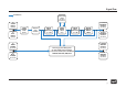
Multichannel Mastering Console MMC 2 Sources Stereo Input A Stereo Input B Stereo Return A Stereo Return B M-CH. Input A M-CH. Input B M-CH. Return A M-CH. Return B M-CH. Return C M-CH. Return D Dim Dim 1 -10 dB Stereo B Dim 2 -20 dB M-CH. A Dim 3 -30 dB M-CH.
Multichannel Mastering Console MMC 2, Model 2486 Manual Manual Version 1, 10/2005 R & D: Wolfgang Neumann The information in this document has been carefully verified and is assumed to be correct. However Sound Performance Lab (SPL) reserves the right to modify the product described in this manual at any time. Changes without notice. This document is the property of SPL and may not be copied or reproduced in any manner, in part or full without the authorization of SPL.
Contents Fade In ................................................................................................ 4 Monitor Level ...................................................................................... 9 Signal Flow .......................................................................................... 5 Option: MasterBay ............................................................................. 10 Front Panel .....................................................................
Fade In Master Fader Moreover additional prerequisites speak for the employment of high-performance analog technology: The number of necessary AD/DA conversions should be reduced to a minimum. With the MMC 2, digital sources can be connected to a digital router, which outputs the selected source through the preferred DA converter. This ensures that the sound quality remains comparable and is not affected by converter differences.
Signal Flow 8 channel bus insert send/ return (bal. drivers and receivers) 2x STEREO INPUTS (balanced) 2x M-CH. INPUTS 4x STEREO RECORDING OUTPUTS PHASE REVERSE switch (passive) Balanced input receivers TRIM ON switch/ TRIM control +/- 10 dB INSERT BYPASS switch (relay) TRIM ON switch/ TRIM control +/- 10 dB MASTER FADER ON/ MASTER FADER (bal. drivers) 2x M-CH. RECORDING OUTPUTS (balanced) (bal. drivers) 2x STEREO RETURNS 2x STEREO MONITOR OUTPUTS (bal. receiver) 4x M-CH. RETURNS (bal.
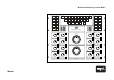
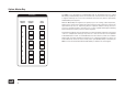
Front Panel Sources Stereo Input A Stereo Input B Stereo Return A Stereo Return B M-CH. Input A M-CH. Input B M-CH. Return A M-CH. Return B M-CH. Return C M-CH. Return D Dim Dim 1 -10 dB Stereo B Dim 2 -20 dB M-CH. A Dim 3 -30 dB M-CH.
Control Elements Sources Sources The Sources section provides selection options for several stereo and multichannel input and return sources. The returns are ideally suited to select recorders, DAW, audio players, and so on. All Input buttons allow for switching between the input monitoring mode and the output monitoring mode. Press once, the input button is permanently illuminated. The output signal after the Master Fader is monitored. Press again, the Input button flashes.
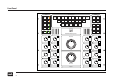
Control Elements Insert/Return Insert On Return On Insert Return The MMC 2 offers an Insert/Return point after the Input Trims to include external processing equipment into the signal path. Monitoring Speaker Management Solo to Center L C R LS RS LFE L t/o R t/o Solo Solo Solo Solo Solo Solo Solo Solo Mono L/R Stereo Operation Mono LS/RS M-CH.
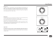
Control Elements Monitor Level The Monitor Level is controlled with a custom-made eight-tiered potentiometer. The MMC 2 does not employ DACs, step ladders or VCAs for this function, and the specifications of this potentiometer are substantially better than either of these other options ever could be – the maximum tolerance is ‹ 0,5 dB over the entire control range. The control range reaches from -∞ dB to +4 dB.
Option: Master Bay The MMC 2 can optionally be complemented with an automated insert box called MasterBay. The MasterBay consists of an 8U insert box and a remote control panel. Up to eight 8-channel processors can be connected to the insert box, which is operated by the MasterBay remote panel.
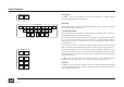
R t/o 8 L t/o 7 RS 5 LS 5 LFE 4 C 3 K U A C A N H M A E A R D P J C B F S A A A K A D A P A L V N A L W T A F A S X A B A M Y A H A T REC OUT M-CH.
Measurements Audio Precision INPUT/OUTPUT PHASE vs FREQUENCY 09/20/05 11:41:11 Audio Precision MMC2 Channel 1 Direct,Pre,Insert,Return to Monitor Out +40 +30 +20 +20 +10 +10 +0 -10 d e g -20 -10 -20 -30 -30 -40 -40 -50 -50 -60 -60 -70 20 50 100 200 500 1k 2k 5k 10k 20k -70 20 50k 100k 50 100 200 500 1k Hz 09/20/05 11:47:37 Audio Precision MMC2 Channel 3 Direct,Pre,Insert,Return to Monitor Out INPUT/OUTPUT PHASE vs FREQUENCY 20k 50k 100k +20 +20 +10 +10 +0
Measurements Audio Precision INPUT/OUTPUT PHASE vs FREQUENCY 09/20/05 11:50:46 Audio Precision MMC2 Channel 5 Direct,Pre,Insert,Return to Monitor Out +30 +20 +10 +10 +0 +0 -10 d e g -20 -20 -30 -30 -40 -40 -50 -50 -60 -60 -70 20 50 100 200 500 1k 2k 5k 10k 20k -70 20 50k 100k 50 100 200 500 1k Hz 10k 20k 50k 100k SPL IN-OUT PHASE.
Measurements Audio Precision INPUT/OUTPUT PHASE vs FREQUENCY Audio Precision MMC2 Input to Monitor Out Channel 1-8 +40 d e g 09/20/05 14:40:05 +25 +20 +20 +10 +15 +0 d e g -10 +10 +5 -20 +0 -30 -5 -40 -10 50 100 200 500 1k 2k 5k 10k 20k -15 20 50k 100k 50 100 200 500 1k Hz 5k 10k 20k 50k 100k Measures phase difference between Input to DUT and Output from DUT. Optimize to see the entire range. SPL IN-OUT PHASE.at2c SPL IN-OUT PHASE.
Measurements Audio Precision MASTER FADER GAIN - FREQUENCY RESPONSE 09/21/05 09:44:19 MMC2 MONITOR GAIN CH 1-8 L R +10 +0 -10 -20 -30 d B r -40 A -50 -60 -70 -80 -90 20 50 100 200 500 1k 2k 5k 10k 20k Hz Frequency Response from 20k to 20 Hz. F4 first to set 0 dBr at 1kHz. The 2 Ch Ampl Function Reading meter BW is set to <10 Hz >500kHz so the bandwidth is the same as the Level meter. Optimize for detail. Pegel In-Out.
Measurements Audio Precision LFE to LCR cal. to -10dB 09/26/05 15:29:10 +20 +17.5 +15 +12.5 +10 +7.5 +5 d B r A +2.5 +0 -2.5 -5 -7.5 -10 -12.5 -15 -17.5 -20 20 50 100 200 500 1k 2k 5k 10k 20k Hz Frequency Response from 20k to 20 Hz. F4 first to set 0 dBr at 1kHz. The 2 Ch Ampl Function Reading meter BW is set to <10 Hz >500kHz so the bandwidth is the same as the Level meter. Optimize for detail. Pegel In-Out.
Measurements Audio Precision GAIN - FREQUENCY RESPONSE 09/21/05 09:19:30 MMC2 PRE TRIM/POT CH 1-8 +20 +17.5 +15 +12.5 +10 +7.5 +5 d B r A +2.5 +0 -2.5 -5 -7.5 -10 -12.5 -15 -17.5 -20 20 50 100 200 500 1k 2k 5k 10k 20k Hz Frequency Response from 20k to 20 Hz. F4 first to set 0 dBr at 1kHz. The 2 Ch Ampl Function Reading meter BW is set to <10 Hz >500kHz so the bandwidth is the same as the Level meter. Optimize for detail. Pegel In-Out.
Measurements Audio Precision MASTER MONITOR GAIN - FREQUENCY RESPONSE 09/21/05 09:47:00 MMC2 MONITOR GAIN CH 1-2 PAD 10,20,30dB L R +0 -2.5 -5 -7.5 -10 d B r -12.5 A -17.5 -15 -20 -22.5 -25 -27.5 -30 20 50 100 200 500 1k 2k Hz Frequency Response from 20k to 20 Hz. F4 first to set 0 dBr at 1kHz. The 2 Ch Ampl Function Reading meter BW is set to <10 Hz >500kHz so the bandwidth is the same as the Level meter. Optimize for detail. Pegel In-Out.
Specifications/Power Supply Dynamic Range ›130 dB Max. input level ›30 dBu (Audio Precision generator limit +30 dBu) THD & Noise (+24 dBu) Recording Out: Monitor Out: Send: ›110 dBu ›108 dBu ›110 dBu Input impedance (balanced): 20 kOhm (Welwyn precision resistors, transformerless) Output impedance (balanced): ‹75 Ohm (CMR trimmers, transformerless) Dimensions Front panel Housing incl. connectors (H x W x D) Weight 19 inch/11U 51.6 x 48.2 x 52 cm/20,3 x 19 x 20.
Warranty SPL electronics GmbH (SPL) products are warranted only in the country where purchased, through the authorized SPL distributor in that country, against defects in material or workmanship. The specific period of this limited warranty shall be that which is described to the original retail purchaser by the authorized SPL dealer or distributor at the time of purchase.