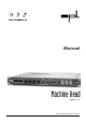
Manual Machine Head Model 9737 Digital Tape Saturation Processor
SOUND PERFORMANCE LAB MACHINE HEAD MODEL 9737 Manual by Hermann Gier Version 1.3 – 1/1999 The information in this document has been carefully verified and is assumed to be correct. However Sound Performance Laboratory (SPL) reserves the right to modify the product described in this manual at any time. Changes without notice. This document is the property of SPL and may not be copied or reproduced in any manner, in part or full without the authorization of SPL.
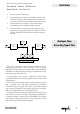
Foreword Thanks Introduction Operation Safety Connections Installing Updates Quick Start Analogue Tape Recording Signal Flow Control Elements ACTIVE INPUT GAIN DRIVE HF-ADJUST OUTPUT GAIN HIGH TAPE SPEED LC-DISPLAY LED CHAINS PRESETS INFO (HARDWARE DIALOGUE) Specifications Warranty 3 3 4 5 6 6 7 7 8 8 8 8 9 10 10 10 10 11 11 15 16 Dear customer, Thank you for the confidence you have shown towards SPL electronics GmbH by purchasing the SPL MACHINE HEAD.
Introduction Creating authentic tape saturation effects. The sound becomes warmer and more powerful, eliminating the harshness of digital recordings.
Indicators and meters: MACHINE HEAD is equipped with PPM displays for input and output levels. The first LED of each input and output meter is a signal (SIG.) LED which illuminates when a compatible digital data stream is present at the inputs. The LEDs are a first indicator to check the data stream. If the LEDs do not illuminate the data stream is interrupted or invalid.
Connections Before connecting the MACHINE HEAD switch the power off at all connected units. The rear panel provides AES/EBU- and S/P-DIF-inputs and outputs. Any additional channel, status and user-bits are passed through unaltered, and the outputs can be used at the same time if required. The MACHINE HEAD operates with 24 bit word width. It accepts 16 to 24 bit inputs and will create output signals according to the input resolution.
All controls are in the start-off positions: Quick Start INPUT GAIN 0, DRIVE 0, HF-ADJUST 0, OUTPUT GAIN 0, TAPE SPEED 15 1. Press ACTIVE. LED illuminates. 2. Increase the DRIVE-value to saturate the “virtual” tape. Set DRIVE to about 6. If the output level increases, use the OUTPUT GAIN control to compensate for the increase. 3. If more saturation is wanted, it may be necessary to reduce the INPUT GAIN slightly to prevent clipping. 4.
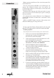
Control Elements 7 5 2 3 Active 4 1 6 9 1 8 10 The ACTIVE function switches the MACHINE HEAD on or off. The illuminated LED indicates that the processing has been activated. The software bypass also compensates for the 5ms time delay between processed and unprocessed signal. Relay hard-bypass for AES/EBU input and output The AES/EBU input and output are equipped with relayhard-bypass.
Recommended values are 3 to 8 for the DRIVE-parameter which corresponds with +10 dB to +15 dB for the actual DRIVE LEVEL shown in the LED meter bar. Practical values for the DRIVE are 3 to 8. When booting the MACHINE HEAD the default value of the DRIVE parameter will be 0 in the LC-display. If you have “the perfect pitch” you can already hear slight saturation effects.
Control Elements Output Gain 5 OUTPUT GAIN varies the output level of the digital data stream. It is variable between -12 dB and +12 dB in 0.1 dB steps. The adjusted OUTPUT GAIN value is shown in the LC-display (see 7) and in the OUTPUT PPM meter (see 8). Compensating a level and/or loudness increase due to processing In practice you will start with the OUTPUT GAIN set to 0 dB. In case you have used high DRIVE values you will use the OUTPUT GAIN to compensate for the slight level increase.
Control Elements The DRIVE LEVEL metering shows the recording level of the “virtual tape machine”. The display range is -10 dB to +21 dB. The DRIVE LEVEL ist adjusted with the DIRVE control (see 3). The OUTPUT PPM meters show the peak level after the OUTPUT GAIN control (see 5). The first LED in each INPUT and OUTPUT PPM meter is a signal (SIG.) LED to indicate that a valid digital source is connected and detected. This LED helps you to verify the signal flow within a digital processing chain. If one SIG.
Control Elements Info 10 Depressing STORE and APPLY simultanouesly for about one second gets you into a hardware dialogue, called INFO. The LCdisplay shows status informations of the digital data stream. With UP/DOWN you will jump from one page to the next or previous. If a selection is provided use APPLY to select. 1. Software version and date 2. Selecting inputs: The MACHINE HEAD automatically searches for an input signal. If both inputs are connected the AES/EBU input will be selected first.
S/P-DIF with wordclock detected or: S/P-DIF input without wordclock is detected 3. Control Elements Press APPLY (if S/P-DIF is detected): Displaying the detected sample frequency: The SAMPLE FREQUENCY will be detected automatically. The display either shows 44,1 kHz, 48 kHz or 32 kHz. 4. Displaying the Audio-Error flag: NO = no error detected; YES = error detected 5. Displaying the CRC-Error flag: NO = no error detected; YES = error detected 6.
Control Elements 9. Displaying the Emphasis flag: NO = no emphasis; YES = with emphasis 10. Selecting a serial port: RS-232 interface for update-download from PCs or (press APPLY): RS-422 interface for update-download from MACs. 11. Selecting a MIDI channel: Depress APPLY to step from MIDI CHANNEL 01 up to MIDI CHANNEL 16. In order to increase operation safety only send the necessary MIDI data to the MACHINE HEAD. Unnecessary information may lead to system failure.
Input/Output Sample rate frequency, autom.
Warranty SPL electronics GmbH (hereafter called SPL) products are warranted only in the country where purchased, through the authorized SPL distributor in that country, against defects in material or workmanship. The specific period of this limited warranty shall be that which is described to the original retail purchaser by the authorized SPL dealer or distributor at the time of purchase.