Manual Spectralizer Model 9631 Digital Harmonics Processor
SOUND PERFORMANCE LAB SPECTRALIZER MODEL 9631 Manual by Hermann Gier and Paul White Version 2.2 – 1/1999 The information in this document has been carefully verified and is assumed to be correct. However Sound Performance Laboratory (SPL) reserves the right to modify the product described in this manual at any time. Changes without notice. This document is the property of SPL and may not be copied or reproduced in any manner, in part or full without the authorization of SPL.
Foreword Thanks Introduction Operation Safety Connections, installing Updates Quick Start Flow Chart Control Elements ACTIVE INPUT GAIN FREQUENCY MIX 2ND HARMONIC 3RD HARMONIC DENSITY LC-DISPLAY SOLO KICK PRESETS INFO (Hardware dialogue) OUTPUT PPM Specifications Warranty 3 3 4 5 6 7 7 Contents 8 8 9 9 9 10 11 11 11 11 11 12 15 16 17 Dear customer, Thank you for the confidence you have shown towards SPL electronics GmbH by purchasing the SPL SPECTRALIZER.
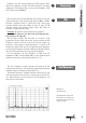
Introduction Re-synthesizing second and third harmonics separately Improving clarity, intelligibility and depth without introducing harshness Warm and smooth sounding harmonic re-synthesis SPL digital audio processors are designed in cooperation with Spectral Design of Bremen, Germany, who are responsible for the DSP programming.
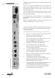
the small timing glitches that would otherwise occur when switching the process in and out. Up to 99 presets can be stored and changed using a MIDI program change command. Display: The SPECTRALIZER is equipped with two PPM-meters that feature high resolution in the important region immediately before 0dB. Clip-LEDs indicate digital clipping, while the first LED of each PPM-meter functions as a signal present indicator to confirm that a digital signal is present at the input.
Connections Before connecting the SPECTRALIZER switch the power off at all connected units. The rear panel provides AES/EBU- and S/P-DIF-inputs and outputs. Any additional channel, status and user-bits are passed through unaltered, and the outputs can be used at the same time if required. The SPECTRALIZER operates with 24 bit word width. It accepts 16 bit and 20 bit inputs and will create output signals according to the input resolution.
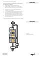
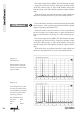
Set all controls to the starting positions: INPUT GAIN 0; FREQUENCY 1k; DENSITY 0; 2ND HARMONIC 0%; 3RD HARMONIC 0%; MIX 0%. 1. Depress ACTIVE. The status-LED illuminates. 2. Set MIX to 50%. You will notice an increase in high frequencies above 1 kHz (starting position FREQUENCY). 3. Set DENSITY to 1, to increase the audibility of the harmonics in the next step. 4. Set 2ND HARMONIC to 50% and 3RD HARMONIC to 30%. 5.
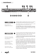
Control Elements 8 9 10 2 3 Active 7 1 INPUT GAIN = 0 for processing pre-production material with enough headroom Choose negative INPUT GAIN values for full scale recordings to create new headroom to add harmonics Use positive INPUT GAIN values for low level material 8 6 4 1 13 12 The ACTIVE function switches the SPECTRALIZER on or off. The illuminated LED indicates that the processing is activated.
3 Frequency MIX controls the mix level between the processed and the unprocessed signal. The control range is 0 % to 100 %. The MIX encoder is equipped with an „alpha-dial“ logic. Turning the encoder rapidly causes the values to jump in steps of 10, whereas turning the encoder slowly causes the values to proceed in single increment steps. 4 Mix 5 2nd Harmonic Control Elements FREQUENCY sets the starting frequency of the highpass filter.
Control Elements The control range is 0 % to 100 %. The 2ND HARMONIC encoder is equipped with alpha-dial logic. Turning the encoder rapidly causes the values to jump in steps of 10, whereas turning the encoder slowly causes the values to proceed in single increment steps. If the need arises to make the harmonics more audible use the DENSITY control (see DENSITY, 7) to increase their loudness.
DENSITY increases the loudness of the generated harmonics by applying different “compression ratios”. The control offers six positions. Density 8 LC-display The SOLO function switches the original input off. You will hear the effect signal only to be able to monitor the highpass-filtering and harmonics generation. 9 Solo The KICK function boosts the amplitude of the generated harmonics in the event of creation (attack-period). After that the amplitude drops back to its original value.
Control Elements Applying a preset: Depress APPLY for1 sec., LED flashes; use UP/DOWN to select preset no.; depress APPLY again, LED goes out If you want to apply various presets depress APPLY for one second. The APPLY LED starts to flash indicating that the APPLY mode is activated. You can step through the preset list with UP and DOWN. Once you have a preset that you want to apply depress APPLY again. The APPLY LED goes out indicating that the preset is applied.
AES/EBU input without wordclock is detected Press APPLY : S/P-DIF input detected Control Elements or: or: no S/P-DIF input detected Press APPLY (if S/P-DIF is detected): S/P-DIF with wordclock detected or: S/P-DIF input without wordclock is detected 3. Displaying the detected sample frequency: The SAMPLE FREQUENCY will be detected automatically. The display either shows 44,1 kHz, 48 kHz or 32 kHz. 4. Displaying the Audio-Error flag: NO = no error detected; YES = error detected 5.
Control Elements 6. Displaying the Channel Difference Error flag: NO = no error detected; YES = error detected 7. Setting or erasing the Copy-Prohibit flag: NO = flag erased or not set; YES = flag set 8. Displaying the Original flag: NO = no Original flag; YES = Original 9. Displaying the Emphasis flag: NO = no emphasis; YES = with emphasis 10. Selecting a serial port: RS-232 interface for update-download from PCs or (press APPLY): RS-422 interface for update-download from MACs. 11.
In order to increase operation safety only send the necessary MIDI data to the SPECTRALIZER. Unnecessary information might lead to system failure. You can use MIDI to create a MIDI fade out, if you are working with a digital console that does not provide master inserts. The UP and DOWN LEDS illuminate indicating that a volume change command is received. You can also switch between presets with the MIDI program change command.
Specifications Input/Output Sample rate frequency, autom.
SPL electronics GmbH (hereafter called SPL) products are warranted only in the country where purchased, through the authorized SPL distributor in that country, against defects in material or workmanship. The specific period of this limited warranty shall be that which is described to the original retail purchaser by the authorized SPL dealer or distributor at the time of purchase.