
Manual
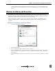

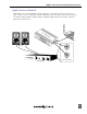
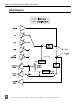
Table Of Contents
- Table of Contents
- Computer System Requirements
- Quick Start Guide
- Front Panel Descriptions
- Input and Output Panel Descriptions
- Back Panel Descriptions
- DIP Switch Options
- Mac OS Installation and Connection
- Windows Installation and Connection
- Inputs
- Outputs and Monitoring
- Stand-Alone Mode
- Locking Sample Rate to External Sources
- Setup Examples
- Block Diagram
- Specifications
- Warranty and Technical Support
- CE Declaration of Conformity

USBPre 2 User Guide and Technical Information
12
Features and specifications are subject to change. Visit www.sounddevices.com for the latest documentation.
Click the 4. Audio tab. Select the USBPre 2 from the Default device dropdown menu in the Sound play-
back section. Select the USBPre 2 from the Default device dropdown menu in the Sound recording
section.
Inputs
Input Source Selection
The USBPre 2 has two available input channels. The source for each input is independently selected
using the Input Select Buttons on the front panel. The selected source is indicated by an illuminated
LED next to the respective Input Select Button. The Input Select Buttons can be locked to prevent ac-
cidental switching of the input sources. See DIP Switch Options.
Microphone Inputs
Phantom Power
The USBPre 2 provides 48-volt phantom power for condenser microphones connected to the XLR
inputs. Phantom power can be engaged independently for each input. See DIP Switch Options. Con-
denser microphones that can operate on phantom voltages from 11-52 volts will function properly
with 48-volt phantom.
Dynamic microphones typically do not require phantom power. A properly connected balanced,
dynamic microphone is not affected by the presence of phantom power nor will it draw any current.
However, it is good practice to turn phantom power off when not needed. Poor or incorrectly wired
microphone cable can cause audible artifacts in microphone signals. Some wireless receivers outputs
are adversely affected by the presence of phantom power, therefore, consult the wireless receiver
documentation.
Low-Cut Filter
The low-cut filter attenuates low frequency signals. This is useful in conditions where low frequency
signal is causing overload before the desired gain is reached (windy environments or handheld mi-
crophones, for example).