TABLE OF CONTENTS 1. General description .......................................................................... 6 2. Indications ......................................................................................... 6 3. Contraindications ............................................................................. 7 4. Warnings and precautions .............................................................. 7 4.1. Risks related to medical environment .................................. 9 4.2.
13. Device description ........................................................................ 35 14. Implant procedure ........................................................................ 38 14.1. Necessary equipment ........................................................ 38 14.2. Packaging ............................................................................ 38 14.3. Optional equipment ............................................................ 39 14.4. Before opening the package ...........
18. Supplemental information ........................................................... 59 18.1. Adverse events in the SafeR study................................... 59 18.2. SafeR clinical study ............................................................ 61 19. Physical characteristics ............................................................... 64 19.1. Materials used ..................................................................... 64 20. Electrical characteristics ..............................
1. GENERAL DESCRIPTION PARADYM RF CRT-D 9750 is an implantable cardioverter defibrillator for the recognition and treatment of ventricular tachycardia and fibrillation, with ventricular resynchronization, in patients with spontaneous or inducible tachyarrhythmias. PARADYM RF CRT-D 9750 is equipped with an accelerometer to allow adaptation of pacing to suit the patient’s activity.
3. CONTRAINDICATIONS Implantation of PARADYM RF CRT-D 9750 is contraindicated in patients: ─ whose ventricular tachyarrhythmias may have transient or reversible causes such as: acute myocardial infarction, digitalis intoxication, drowning, electrocution, electrolyte imbalance, hypoxia, sepsis, or unstable ischemic episodes, ─ who present incessant tachyarrhythmia, ─ who have an internal pacemaker, ─ whose primary disorder is bradyarrhythmias, or atrial tachyarrhythmias.
Be aware that the changes in the patient’s condition, drug regimen, and other factors may change the defibrillation threshold (DFT) which may result in non-conversion of the arrhythmia post-operatively. Successful conversion of ventricular fibrillation or ventricular tachycardia during arrhythmia conversion testing is no assurance that conversion will occur post-operatively.
Home appliances: Home appliances that are in good working order and properly grounded do not usually produce enough EMI to interfere with defibrillator operation. There are reports of device disturbances caused by electric hand tools or electric razors used directly over the device implant site. CAUTION: Do not tap sharply on the ICD can after implant, because the ICD's sensing circuits can detect this as P-waves or R-waves, and such oversensing could result in inappropriate pacing, inhibition, or therapy.
the procedure, check for proper implant function. The device should never be exposed directly to the diathermy source. External defibrillation: PARADYM RF CRT-D 9750 is protected from external defibrillation shocks. Before external defibrillation, deactivate ATP and shock therapies. During external defibrillation, it is advisable to avoid placing the defibrillating paddles directly over the casing or over the leads. The defibrillating paddles should preferably be placed in an anteroposterior position.
4.2. STERILIZATION, STORAGE AND HANDLING Resterilization: Do not resterilize and re-implant explanted ICDs. "Use Before" Date: A "Use Before" date is printed on the outer storage package and on the sterile package. Do not implant the device after this date because the battery may have reduced longevity and sterility may be affected. It should be returned to Sorin CRM.
In situations where an ICD and a pacemaker are implanted in the same patient, interaction testing should be completed. If the interaction between the ICD and the pacemaker cannot be resolved through repositioning of the leads or reprogramming of either the pacemaker or the ICD, the pacemaker should not be implanted (or should be explanted if previously implanted).
4.4. LEAD EVALUATION AND LEAD CONNECTION PARADYM RF CRT-D 9750 has two DF-1 and three IS-1 connector ports. IS-1 refers to the international standard whereby leads and generators from different manufacturers are assured a basic fit (ISO 5841-3:2000). DF-1 refers to the international standard for defibrillation lead connectors (ISO 11318:2002). Do not tie a ligature directly to the lead body, tie it too tightly, or otherwise create excessive strain at the insertion site as this may damage the lead.
leads. While the ICD is connected to the leads, make sure that the metal portions of any electrodes do not touch each other. If a pacing lead is abandoned rather than removed, it must be capped to ensure that it is not a pathway for currents to or from the heart. If a thoracotomy is required to place epicardial patches, it should be done during a separate procedure to reduce the risk of morbidity and mortality. Do not place the patch lead over nerve tissue as this may cause nerve damage.
5. ADVERSE EVENTS Clinical data presented in this section are from the MSP clinical study. PARADYM RF CRT-D is similar in design and clinical function to the ALTO 2 MSP and OVATIO CRT-D devices. The data provided are applicable to PARADYM RF CRT-D. 5.1. MSP STUDY Sorin CRM conducted an international, multi-center, randomized clinical trial of its cardiac resynchronization therapy system. Investigators attempted to implant study devices in 190 patients.
Event # of Patients % of Patients # of Events Events/ 100 DeviceYears Deaths not related to the system 16 8.4 16 0.8 Cardiac arrest 5 2.6 5 0.3 Worsening CHF / CHF decompensation 3 1.6 3 0.2 Multi-organ dysfunction 2 1.1 2 0.1 Complications related to the system 28 14.7 35 2.1 Dislodgment or migration 9 4.7 11 0.6 Extracardiac stimulation (e.g., phrenic stim) 9 4.7 9 0.5 Complications related to the implant procedure 18 9.5 21 1.3 Dislodgment or migration 4 2.
Extracardiac stimulation (e.g., phrenic stim) 3 1.5 5 0.3 Event # of Patients % of Patients # of Events Events/ 100 DeviceYears Serious adverse events not related to the system 85 44.7 176 10.8 Worsening CHF/CHF decompensation 24 12.6 42 2.1 Atrial fibrillation/flutter 14 7.4 14 0.7 Not Serious events not related to the system 58 30.5 121 7.4 Pain (in back, arms, chest, shoulder, groin, head, other) 10 5.3 13 0.7 Worsening CHF/CHF decompensation 13 6.8 16 0.
5.2.
Patients susceptible to frequent shocks despite antiarrhythmic medical management may develop psychological intolerance to an ICD system that may include the following: ─ Dependency, ─ Depression, ─ Fear of premature battery depletion, ─ Fear of shocking while conscious, ─ Fear that shocking capability may be lost, ─ Imagined shocking (phantom shock).
6. CLINICAL STUDIES Clinical data presented in this section are from the MSP clinical study. PARADYM RF CRT-D is similar in design and function to the ALTO 2 MSP and OVATIO CRT-D devices. The data provided are applicable to PARADYM RF CRT-D. 6.1. MSP CLINICAL STUDY OVATIO CRT-D and earlier models were evaluated clinically in an international, multi-center, randomized clinical trial of Sorin CRM’s cardiac resynchronization therapy (CRT-D) system.
Results IMPROVEMENT IN COMPOSITE ENDPOINT Patients were included in the analysis if complete (peak VO 2 and quality of life) baseline and six-month data were available. Number of patients contributing to analysis Mean percent improvement in composite endpoint for control group Mean percent improvement in composite endpoint for CRT-D group Percent greater improvement for CRT-D group p-value 132 15.5 % 24.9 % 9.4 % 0.
Absolute Differences in Peak VO2 and QOL The tables below show the absolute differences between the control and test groups’ peak VO2 and QOL over the 6 month follow-up period in the clinical trial. Change in Peak VO2 (mL/min/Kg) Absolute difference between test and control groups’ change in peak V02 over 6 months Contr ol group (n=41) Baseline Mean ± SD (range) 6-month Mean ± SD (range) Difference within group Difference between groups 13.39 ± 4.58 (5.02, 24.10) 13.12 ± 3.99 (3.30, 20.70) - 0.
The table below presents the percentage of patients in each group who improved, worsened, or remained unchanged in each element of the composite score and the composite score itself. QOL score VO2 Score Composite Score Contro Test l GROUP GROU P Control Test Control GROU GROU GROU P P P Test GROU P % Improved 75.6 74.7 48.8 67.0 62.2 70.9 % Worsened 24.4 25/03/09 51.2 31.9 37.8 28.6 % Unchanged 0.0 0.0 0.0 1.1 0.0 0.
RER at peak VO2 at six months Test Control 60 Percent of patients 50 40 30 20 10 0 ≤ 0.79 0.80-0.89 0.90-0.99 1.0-1.09 1.10-1.19 1.20-1.29 ≥ 1.30 RER Clinical Results V-V timing V-V programmable settings were available for the clinical study devices as follows: ALTO MSP model 617 (not programmable for V-V delay), ALTO 2 MSP model 627 values (0, 31, 39, 47, 55 and 63 ms) and OVATIO CRT-D 6750 values (0 to 63 ms in steps of 8 ms).
The optimization protocol in the clinical study specified that each patient randomized should undergo echo guided V-V optimization. Per the investigational plan for the MSP Clinical Trial, a uniform protocol was used for V-V programming. This protocol required all patients to undergo echo-guided V-V delay optimization before randomization (2 to 14 days post-implant).
7. PATIENT SELECTION AND TREATMENT 7.1. INDIVIDUALIZATION OF TREATMENT Exercise stress testing. If the patient’s condition permits, use exercise stress testing to: ─ Determine the maximum rate of the patient’s normal rhythm, ─ Identify any supraventricular tachyarrhythmias, ─ Identify exercise-induced tachyarrhythmias. The maximum exercise rate or the presence of supraventricular tachyarrhythmias may influence selection of programmable parameters.
Antiarrhythmic drug therapy: If the patient is being treated with antiarrhythmic or cardiac drugs, the patient should be on a maintenance drug dose rather than a loading dose at the time of ICD implantation. If changes to drug therapy are made, repeated arrhythmia inductions are recommended to verify ICD detection and conversion. The ICD also may need to be reprogrammed.
8. PATIENT COUNSELLING INFORMATION The physician should consider the following points in counselling the patient about this device: ─ Persons administering CPR may experience tingling on the patient’s body surface when the patient’s ICD system delivers a shock. ─ Advise patients to carry Sorin CRM ID cards and/or ID bracelets documenting their ICD system. 9.
─ EN 50371 (2002) : Generic standard to demonstrate the compliance of low power electronic and electrical apparatus with the basic restrictions related to human exposure to electromagnetic fields (10 MHz - 300 GHz) ─ EN 301 489-1 (v1.8.1) & EN 301 489-27 (v1.1.
Federal Communication Commission Interference Statement 47 CFR Section 15.19 and 15.105(b) - The FCC product ID is YSGCRTD9750. This equipment has been tested and found to comply with the limits for a Class B digital device, pursuant to Part 15 of the FCC Rules. These limits are designed to provide reasonable protection against harmful interference in a residential installation.
and digital voice communications are prohibited. Although this transmitter has been approved by the Federal Communications Commission, there is no guarantee that it will not receive interference or that any particular transmission from this transmitter will be free from interference. IC Requirements for canada - The IC product ID is 10270A-CRTD9750 This class B digital apparatus meets all requirements of the Canadian Interference- causing equipment regulations.
10. PHYSICIAN GUIDELINES 10.1. PHYSICIAN TRAINING Physicians should be familiar with sterile pulse generator and left ventricular pacing lead implant procedures. They must apply these procedures according to professional medical training and experience. Physicians should be familiar with follow-up evaluation and management of patients with an implantable defibrillator (or referral to such a physician).
10.2. DIRECTIONS FOR USE ICD operating characteristics should be verified at the time of implantation and recorded in the patient file. Complete the Patient Registration Form and return it to Sorin CRM, as it provides necessary information for warranty purposes and patient tracking. Additional programming instructions can be found by accessing Online Help (click the “?” on the screen) on the Sorin CRM dedicated programmer.
11. PATIENT INFORMATION Information for the patient is available in the patient booklet, contained in the outer storage package. Additional copies can be obtained by contacting your Sorin CRM representative or on the Sorin CRM's web site: http://www.sorin.com. This information should be given to each patient with their first ICD and offered to the patient on each return visit or as deemed appropriate. 12. HOW SUPPLIED 12.1.
13. DEVICE DESCRIPTION The PARADYM RF CRT-D system includes the model 9750 ICD device and programming system. The programming system includes the Sorin CRM Orchestra Plus programmer with the SMARTVIEW programming software connected to a CPR3 programming head. The programming system is configured and furnished by Sorin CRM. The PARADYM RF CRT-D 9750 can serves as a defibrillation electrode (active housing) with a total surface area of 76 cm².
PARADYM RF CRT-D 9750 offers tiered therapy. Therapies can be programmed independently in each zone: ─ in the Slow VT and VT zones: two ATP programs, up to two shocks with programmable energy and up to four shocks with maximum energy can be programmed; ─ in the VF zone: one ATP program, up to two shocks with programmable energy and up to four shocks with maximum energy can be programmed. The ATP can be applied in RV, LV or RV and LV pacing with a VV delay equal to 0 ms.
─ Manual ATP sequences, ─ Manual shocks. ─ Rescue shock ─ Follow-up tests: ─ Pacing lead impedance, ─ Coil impedance, ─ Capacitor charge time, ─ Sensitivity test, ─ Pacing threshold tests. ─ Data storage: ─ Therapy History Report, ─ Statistics (pace/sense, therapy, shocks, and battery voltage), ─ Up to 14 complete Holter records with event logs, marker channel notation, and electrogram records.
14. IMPLANT PROCEDURE 14.1.
14.3. OPTIONAL EQUIPMENT The following equipment may be required during implantation of PARADYM RF CRT-D 9750: ─ an IS-1 insulating plug to close the atrial port ─ sterile water to clean traces of blood. Any parts cleaned with sterile water must be thoroughly dried. ─ mineral oil to lubricate if necessary ─ a lead cap to isolate a lead which is not used 14.4. BEFORE OPENING THE PACKAGE Before opening the package, check the "Use Before" date printed on the labels on the box and on the sterile package.
CAUTION: Do not shake or tap sharply on the ICD package with the ICD inside, because the ICD's sensing circuits can interpret this as Pwaves or R-waves and record these as an arrhythmia episode. If unusual shaking or tapping of the package results in a stored arrhythmia episode, erase the recording before using the ICD. 14.6. DEVICE PLACEMENT The pocket should be prepared in the left pectoral position, either subcutaneously or submuscularly.
SHOCK CONFIGURATION (+ -> -) The shock configuration is the energy pathway between the defibrillation electrodes. If an atrial coil is present, the shock configuration can be programmed for bi-directional shocks. Programming: When active case and SVC are both programmed to Yes, the shock configuration can be programmed to: ─ RV to Case (or Case to RV), ─ or RV to SVC (or SVC to RV), ─ or RV to Case+SVC (or Case+SVC to RV). The polarity of shock is determined by the parameter itself.
Pacing impedance measurements: Right ventricular, left ventricular and atrial pacing impedances should range from 200 to 3000 ohms (refer to the lead characteristics, especially if high impedance leads are used). 14.9. LEAD CONNECTION Implant the ventricular leads, then the atrial lead. Each lead must be connected to the corresponding connector port. The position of each connector is indicated on the casing. CAUTION: Tighten only the distal inserts. To connect each lead, proceed as follows: 1.
Caution: 1. One single set screw is located on the side of the connection header. 2. Do not tighten the pre-inserted screws when there is no lead (this could damage the connector). 3. Do not loosen the screws before inserting the connector (subsequent risk of being unable to reinsert the screw). 4. Removing the screwdriver: to avoid all risk of loosening screws during removal, hold the screwdriver by its metal part and not by the handle. 5.
14.11. TESTS AND PROGRAMMING During the implant testing procedure, it is recommended that a security margin of at least 10 J be demonstrated between the effective shock energy and maximum programmable energy. Enable shock therapies, then program the defibrillator. Verify that the defibrillation lead impedance for each shock delivered ranges from 30 to 150 ohms. Check the lead connection if the values are outside these boundaries.
15.2. MAGNET MODE When the magnet is applied: ─ antiarrhythmia functions are inhibited (detection of rhythm disturbances, charging, and therapy), ─ hysteresis, VV delay and AVD paced/sensed offset are set to 0, ─ pacing amplitude is set to 6 V, ─ pulse width is set to maximum, ─ pacing rate is set to the magnet rate, ─ the following functions are disabled: ventricular arrhythmia prevention, Mode Switch, Anti-PMT, Smoothing, Rate Response.
15.3. RESPONSE IN THE PRESENCE OF INTERFERENCE If the defibrillator senses electrical noise at a frequency above 16 Hz, it switches to an asynchronous mode at the basic rate. The programmed mode is restored as soon as the noise is no longer detected. Ventricular pacing is also inhibited by ventricular noise. It can be restored by setting the parameter V pacing on noise to Yes. 15.4. DETECTION CHARACTERISTICS IN THE PRESENCE OF ELECTROMAGNETIC FIELDS Per Clause 27.
Modulated interference: For atrial sensitivity setting of 0.2 mV, compliance to the Cenelec standard 45502-2-2 is met for a maximum test signal amplitude of 8 V for the frequency of 60 MHz. 0.4 mV complies with the standard for the whole frequency range. 15.5. PROTECTION AGAINST SHORT-CIRCUITS The defibrillator can undergo a short-circuit if the anode and cathode are not adequately separated.
16.3. VENTRICULAR TACHYARRHYTHMIA MANAGEMENT Ventricular tachyarrhythmia prevention: Set of algorithms that can be used to avoid the circumstances of ventricular tachyarrhythmia onset. Searching for a long cycle (P And R based Arrhythmia Detection+: PARAD+): Additional arrhythmia classification criterion to improve identification of atrial fibrillation and avoid inappropriate shocks.
Anti-PMT protection: Is intended to protect the patient from Pacemaker-Mediated Tachycardia (PMT) without reducing atrial sensing capability of the device. 16.5. SENSING Automatic Refractory Periods: Optimize sensing and make the implant progamming easier. These periods are composed of a minimal Refractory Period and a triggerable Refractory Period. The duration of the refractory periods lengthens automatically as needed.
16.6. FOLLOW-UP FUNCTION Storage of memory data: AIDA+ (Automatic Interpretation for Diagnosis Assistance) software provides access up to 6 months of patient follow-up with day by day data collection, or up to 24 hours with hourly data collection. Episodes of ventricular tachyarrhythmia are recorded with the programmable EGM channels: either by selecting up to two traces, or by selecting "Double V" which enables a one-channel recording that is twice as long.
SMARTVIEW Monitor The SMARTVIEW monitor is a small device equipped with an RF transmission module to communicate with the implant and a modem to export data through the internet. The SMARTVIEW monitor is delivered to the patient who has to install it at home. Preferably the SMARTVIEW monitor will be placed on the nightstand of the patient, as close as possible to the side of the bed the patient usually sleeps. The SMARTVIEW monitor shall be connected to the phone network and the power plug.
Data transmitted The data transmitted are identical to the data available during a standard interrogation with the Orchestra Plus programmer.
Alert system The following set of alert trigger can be independently programmed ON/OFF by the physician using the Orchestra Plus programmer and can trigger an alert transmission: ─ Reset of the device ─ ERI reached ─ Low or high impedance (A, RV, LV) ─ Abnormal coil impedance (shock lead) ─ Low or High shock impedance ─ Long charge time ─ Inefficient high energy shock ─ All shocks programmed OFF ─ Shock treated VT/VF ─ Lack of V pacing in CRT device ─ Suspicion of noise on the V lead ─ AT/AF occurrence ─
17. PATIENT FOLLOW-UP 17.1.
17.2. HOLTER FUNCTION The Holter records up to 14 tachyarrhythmia episodes as well as the therapy history. STORED EPISODES PARADYM RF CRT-D 9750 stores up to 14 episodes (VF, VT, Slow VT, SVT/ST, nonsustained).
17.3. ELECTIVE REPLACEMENT INDICATOR (ERI) Elective Replacement Indicators (ERI)(1) are: ─ magnet rate equal to 80 ± 1 min-1 or ─ battery voltage equal to 2.66 V ± 0.01 V Caution: The defibrillator should be replaced as soon as the Elective Replacement Indicator (ERI) point is reached. Between the ERI and the EOL (End of Life)(2), PARADYM RF CRT-D 9750 can still function for: ─ 7.
17.4. EXPLANTATION The defibrillator should be explanted in the following cases: ─ The Elective Replacement Indicator (ERI) point is reached ─ Confirmed malfunction ─ Burial of the patient (for environmental reasons, the local regulation may require the explantation of the devices containing a battery supply) ─ Cremation of the patient (the defibrillator may explode if placed in an incinerator). The explanted defibrillator should not be reused in another patient.
17.5. DEFIBRILLATOR IDENTIFICATION The defibrillator can be interrogated and programmed via telemetry, using the programming head interfaced with the Sorin CRM dedicated programmer. Position the programming head over the telemetry antenna located in the upper part of the device, in order to communicate effectively via telemetry (see diagram below). The device can be non-invasively identified as follows: 1.
18. SUPPLEMENTAL INFORMATION Clinical data presented in this section are from the SafeR clinical study. SafeR operation in PARADYM RF is similar to that in the Symphony pacemaker. The data provided are applicable to PARADYM RF CRTD. 18.1. ADVERSE EVENTS IN THE SAFER STUDY Clinical study of the SafeR included 45 Symphony 2550 devices implanted in 45 patients. No serious adverse events were device- or feature-related. There were no deaths in the study. Table 1 summarizes the safety data for this study.
Table 1: Summary of Symphony safety data during study Patients Number of events Number of patients % of patients Number of events Events per device year (a) Deaths 0 0 0 0 Explants 0 0 0 0 Serious pacemaker related events outside the use of SafeR 0 0 0 0 0 Non-serious pacemaker related events outside the use of SafeR 0 0 0 Serious events due to the use of SafeR 0 0 0 0 Non-serious events related due to the use SafeR 13 28.9 15 3.
Non-serious events due to the use of SafeR included: delay in switching on 2nd degree AV block, inappropriate classification of a PAC, disagreement between markers and recorded EGM, atrial pacing above the maximum rate, recycling on an r-wave in a refractory period, and disagreement in the statistics for switches to DDD. No patient symptoms were associated with these events. 18.2. SAFER CLINICAL STUDY SafeR mode in PARADYM RF is similar to that in Symphony.
At pre-discharge, a 24-hour Holter recording was performed and pacemaker memory was read. At one month, pacemaker memory was read. Investigators also documented adverse events. Patients studied: A total of 45 patients from 12 centers had Symphony 2550 pacemakers with SafeR. Of these, 14 (31 %) were female and 31 (69 %) were male. Mean patient age (± SD) was 74 ± 9 years. Primary indications for implant were: 1st degree AV block (11.1 %), 2nd degree AV block (6.7 %), 3rd degree AV block (22.
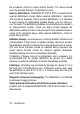
The graph shows that many patients programmed to SafeR had less than 1% ventricular pacing: 84 % of patients without AV block at implant. 63 % of patients with AV block at implant. In a representative reference group1(1) of patients programmed to DDD, none had less than 1 % ventricular pacing and only 10 % had less than 90 % ventricular pacing regardless of AV block indication at implant.
19. PHYSICAL CHARACTERISTICS Dimensions 69.5 x 73.4 x 11 mm Weight 95 g Volume 38.6 cm3 Active surface area of casing 76 cm2 Connector Atrium: IS-1. Right ventricle: IS-1, DF-1. Left ventricle: IS-1. 19.1. MATERIALS USED Active surface area of casing 99% pure titanium Connectors Polyurethane* and silicone elastomer* DF-1 insulating plug silicone elastomer* *Medical-grade materials that have undergone “in vitro” and “in vivo” qualifications.
20. ELECTRICAL CHARACTERISTICS Atrial input impedance 80 kilohms ± 30 % Ventricular input impedance 80 kilohms ± 30 % D.C.
20.1. TABLE OF DELIVERED SHOCK ENERGY AND VOLTAGE The relationship between stored energies, maximum voltages and delivered energies (at 37 °C, 50 ohm load) for the minimum, low, mean and maximum programmed energy values is as follows: Stored energy (J) 0.5 10 20 34 42 V1 (Volt) 75 341 483 631 702 V2 (Volt) 37 173 245 318 353 Delivered E: Phase 1 (J) 0.31 7.0 14.0 23.9 29.6 Delivered E: Phase 2 (J) 0.08 1.8 3.6 6.1 7.5 Delivered E: Total (J) 0.4 8.8 17.6 30.0 37.
20.3. LONGEVITY The longevities mentioned below are calculated by taking into account 6 months storage. 5.1 years Biventricular pacing in DDD mode, 100%, 500 ohm, 3.5 V, 0.35 ms, 60 min-1, one 42 J shock per quarter, sensor OFF 5.0 years Biventricular pacing in DDD mode, 100%, 500 ohm, 3.5 V, 0.35 ms, 60 min-1, one 42 J shock per quarter, sensor ON 6.0 years Biventricular pacing in DDD mode, 1% in atrium, 100% in both ventricles, 500 ohm, 3.5 V, 0.
The mean longevity as a function of yearly remote follow-ups(1), with and without pacing, is as follows: (1) An excessive number of remote follow-up can have a non-negligible impact on device longevity.
21. PROGRAMMABLE PARAMETERS measured at 37 °C under a 500 ohm load Legend: Value in bold: “as shipped” value Underlined value: nominal value 21.1.
Special features Values Smoothing OFF-Very slow-Slow-Medium-Fast Mode Switch ON-OFF Mode Switch Rate (min-1) From 30 to 90 by steps of 5 ; 60 Physical activity Very low-Low-Medium-High-Very high Exercise AV opt. rate (min-1) From 70 to 120 by steps of 5; 90 Pacing/Sensing Values Atrial sensitivity (mV) (1) From 0.2 to 4 by steps of 0.2 ; 0.4 (± 50 %) Atrial amplitude (V) (2) 1-1.5-2-2.5-3-3.5-4-4.5-5-6 (± 20 %) Atrial pulse width (ms) 0.12-0.25-0.35-0.5-0.6-0.75-0.
(1) Values are measured using a positive and negative triangular signal of 2/13 ms. (2) The correlation between the programmed amplitudes, the stored amplitudes and the mid-pulse delivered amplitudes under a 500 ohm load are given in the following table: Programmed ampl. (V) 0.25* 0.5* 0.75* 1 1.25* 1.5 Mid-pulse delivered ampl. (V) 0.28 0.49 0.76 0.97 1.18 1.39 Stored amplitude (V) 0.33 0.57 0.89 1.14 1.38 1.63 Programmed ampl. (V) 1.75* 2 2.25* 2.5 2.75* 3 Mid-pulse delivered ampl.
Post-shock mode Values Mode OFF-VVI-DDI-DDD Duration 10s-20s-30s-1min-2min-3min-4min-5min Basic rate (min-1) From 50 to 90 by steps of 5 ; 60 (± 4 %) Rest AV delay (ms) 30-40-45-55-65-70-80-85-95-100-110-115125-135-140-150-155-165-170-180-190195-205-210-220-225-235-250 (± 19 ms) Exercise AV delay (ms) 30-40-45-55-65-70-80-85-95-100-110-115125-135-140-150-155-165-170-180-190195-205-210-220-225-235-250 (± 19 ms) AVD Paced/Sensed Offset (ms) 0-10-15-25-30-40-45-55-65-70-80-85-95100-110-115-125 (±
Refractory periods Values Atrial refractory period post ventricular sensing (ms) 45-65-80-95-110-125-140-155 (± 16 ms) Atrial refractory period post ventricular pacing (ms) 80-95-110-125-140-155 (± 4 ms) Sensitivity margins Values Atrial post pacing/sensing margin (mV) From 0 to 1 by steps of 0.2 ; 0.4 Ventricular post pacing margin (mV) From 0 to 2 by steps of 0.2 ; 0.
21.2.
Detection criteria Values Slow VT and VT detection criteria Rate Only-Stability-Stability+Stability/Acc-Stability+/Acc-PARADPARAD+ Fast VT detection criteria Rate+Stability-Rate Only Majority: (X/Y), Y (cycles) 8-12-16 Majority: (X/Y), X (%) 65-70-75-80-90-95-100 Window of RR stability for Slow VT and 30-45-65-80-95-110-125-125 VT (ms) Window of RR stability for fast VT (ms) 30-45-65 Prematurity acceleration (%) 6-13-19-25-31-38-44-50 Long cycle persistence extension (cycles) From 0 to 16 by
21.3.
ATP 2 program Values ATP program OFF-Burst-Burst+Scan-RampRamp+Scan Number of sequences 1-2-3-4-5-6-7-8-9-10-11-12-13-14-15 Cycles in first sequence 1-2-3-4-5-6-7-8-9-10-11-12-13-14-15 Cycles added per sequence 0-1-2-3-4-5-6-7-8-9-10-11-12-13-14-15 Coupling interval (%) 50-55-60-65-70-75-80-85-90-95 Ramp decrement (per cycle) (ms) 0-4-8-12-16-20-30-40-50-60 Scan decrement (per sequence) (ms) 0-4-8-12-16-20-30-40-50-60 Time limit (min) 0.5-1-1.5-2-2.5-3-3.
Therapy parameters in VT zone ATP 1 program Values ATP program OFF-Burst-Burst+Scan-RampRamp+Scan Number of sequences 1-2-3-4-5-6-7-8-9-10-11-12-13-14-15 Cycles in first sequence 1-2-3-4-5-6-7-8-9-10-11-12-13-14-15 Cycles added per sequence 0-1-2-3-4-5-6-7-8-9-10-11-12-13-14-15 Coupling interval (%) 50-55-60-65-70-75-80-85-90-95 Ramp decrement (per cycle) (ms) 0-4-8-12-16-20-30-40-50-60 Scan decrement (per sequence) (ms) 0-4-8-12-16-20-30-40-50-60 Time limit (min) 0.5-1-1.5-2-2.5-3-3.
Shock program Values Shock 1 (J) OFF-0.5-0.8-1-1.3-1.5-2-2.5-3-3.5-4-5-67-8-9- (± 30 %) 10-12-14-16-18-20-22-24-26-28-30-3234-42 (± 15 %) Shock 2 (J) OFF-0.5-0.8-1-1.3-1.5-2-2.5-3-3.5-4-5-67-8-9- (± 30 %) 10-12-14-16-18-20-22-24-26-28-30-3234-42 (± 15 %) Number of Max.
Shock program Values Shock 1 (J) OFF-0.5-0.8-1-1.3-1.5-2-2.5-3-3.5-4-5-67-8-9- (± 30 %) 10-12-14-16-18-20-22-24-26-28-30-3234-42 (± 15 %) Shock 2 (J) OFF-0.5-0.8-1-1.3-1.5-2-2.5-3-3.5-4-5-67-8-9- (± 30 %) 10-12-14-16-18-20-22-24-26-28-30-3234-42 (± 15 %) Number of Max. Shock (42 J) 1-2-3-4 21.4. REMOTE ALERTS AND WARNINGS General parameters Values RF communication (1) ON-OFF Remote alerts (1) ON-OFF (1) RF and Remote alerts are turned on automatically if Shocks are programmed ON.
Lead Alerts Values Abnormal A lead impedance ON-OFF Abnormal A lead low limit (Ohm) 200-250-300-350-400-450-500 Abnormal A lead high limit (Ohm) 1500-1750-2000-2500-3000 Abnormal RV lead impedance ON-OFF Abnormal RV lead low limit (Ohm) 200-250-300-350-400-450-500 Abnormal RV lead high limit (Ohm) 1500-1750-2000-2500-3000 Abnormal LV lead impedance ON-OFF Abnormal LV lead low limit (Ohm) 200-250-300-350-400-450-500 Abnormal LV lead high limit (Ohm) 1500-1750-2000-2500-3000 Abnormal RV co
Therapy information Values Shock disabled ON-OFF Shocks delivered OFF-All shocks-Inefficient shockInefficient max shock 22.
23. LIMITED WARRANTY The PARADYM RF implantable cardioverter defibrillator is the result of highly advanced research and all components have been selected after exhaustive testing. Sorin CRM S.r.l.
4. The limited guarantee only applies to suspect devices returned to the manufacturer, carefully packed and accompanied by an explantation report duly completed by the hospital or the doctor and considered defective after analysis by Sorin CRM. The device must be returned within the 30 days following explantation to Sorin CRM. Any device returned and replaced under the terms of this limited warranty will become the exclusive property of Sorin CRM.
23.2. ARTICLE 2 : TERMS OF REPLACEMENT 1. In case of PARADYM RF failure because of a component failure, a production defect, or a conception error, occurring within two-year period starting from the implantation date, Sorin CRM is committed to: replacing free of charge the explanted device by a Sorin CRM device with equivalent features, or issuing a replacement credit equal to the purchase price for the purchase of any other Sorin CRM replacement device.
24.
25.
FCC ID YSGCRTD9750 IC : 10270A-CRTD9750 Last revision date of this implant manual: 2012-05 88 – US-ENGLISH