
User's Manual


9
CPR4 – UA10821A
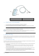
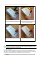
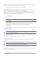
The following pictures show how to use the LEDs to find the best position for the CPR4:
No detection (pair of white alternating LEDs )
Partial detection (two steady white LEDs).
Indication to mode the head downwards.
Full detection (four steady white LEDs) but not optimal
position (only two blue LEDs)
Full detection (four steady white LEDs) and best
position (four blue LEDs)
For optimal telemetry, you are advised to keep the inductive programming head away from electromagnetic
interference, which can be generated by any electronic equipment including medical equipment.
Avoid establishing telemetry communication between the programmer and the implanted device when the
Programmer is close to monitors, high frequency electrocautery equipment, external defibrillator or strong
magnetic fields. The telemetry link might be impaired.
5.2 Troubleshooting
As the CPR4 is powered through the USB port of the programmer, the first requirement for the CPR4 to properly
work is that the programmer is fully functional, and suitable for the use with the CPR4. Please consult your MicroPort
correspondent in case of any doubt about the compatibility of your programmer with the CPR4.