
User Manual
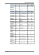
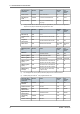
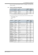
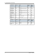
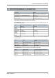
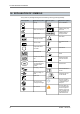
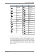
Table Of Contents
- 1. General description
- 2. Intended use and targeted population
- 3. Contraindications and adverse events
- 4. Warnings
- 5. Clinical studies
- 6. Patient selection and treatment
- 7. Patient counseling information
- 8. Declaration of conformity
- 9. Physician guidelines
- 10. Patient information
- 11. How supplied
- 12. Implant procedure
- 13. Pacemaker interrogation and upgrade
- 14. Special modes
- 15. Functions and parameters
- 16. Patient follow-up
- 17. Standby mode
- 18. Medical follow-up
- 19. Physical characteristics
- 20. Electrical characteristics
- 21. Programmable parameters
- 22. Non-programmable parameters
- 23. Warranty
- 24. Explanation of symbols

NOTE: The Automatic implant detection function is not available in a SR model when A
chamber is selected.
REMOTE ALERTS AND WARNINGS
General parameters Models Values Nominal
value
"As
shipped"
value
RF communication
(1)
SR, DR
ON-OFF ON OFF
Alerts SR, DR
ON-OFF ON ON
(1) The nominal value depends on the state of the battery (residual capacity)
When Alerts are programmed "ON", the following System Alerts are automatically activated:
― “Battery depletion – RRT”
― “System integrity”
― Reset
Lead Alerts Models Values Nominal
value
"As
shipped"
value
Abnormal A lead
impedance
SR, DR
ON-OFF ON ON
Abnormal A lead
low limit (Ω)
SR, DR
200-250-300-350-400-450-500 300 300
Abnormal A lead
high limit (Ω)
SR, DR
1500-1750-2000-2500-3000 2000 2000
Atrial
autothreshold
DR
ON-OFF ON ON
Atrial high
threshold limit (V)
DR
1-1.25-1.5-1.75-2-2.25-2.5-3-3.5-
4
2.5 2.5
Atrial Lead Polarity
Switch
DR
ON-OFF ON ON
Abnormal V lead
impedance
SR, DR
ON-OFF ON ON
Abnormal V lead
low limit (Ω)
SR, DR
200-250-300-350-400-450-500 300 300
Abnormal V lead
high limit (Ω)
SR, DR
1500-1750-2000-2500-3000 2000 2000
Ventricular
Autothreshold
SR, DR
ON-OFF ON ON
Ventricular high
threshold limit (V)
SR, DR
1-1.25-1.5-1.75 1.75 1.75
Ventricular lead
polarity switch
SR, DR
ON-OFF ON ON
21.2.
21. PROGRAMMABLE PARAMETERS
ALIZEA – UA10414A 73