
Instruction Manual

Form 925 (08.13) ©SOR Inc.
9/16
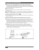
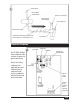
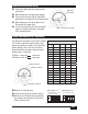
Adjustable Differential Set Up
Differential
Adjustment
Loop Power TerminalsLED’s
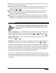
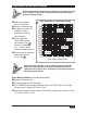
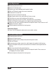
Delay Timer Operation (DT accessory)
The delay timer is present in units which contain
a DT near the end of the model number. Time
delays are available as shown in the Time Delay
Switch Settings chart. Two sets of switches
located inside the electronics housing control
the delay timer (see below).
On Delay = sensor dry
sensor wet
Off Delay = sensor wet
sensor dry
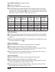
Time Delay Switch Setting
Delay
(Seconds)
Position
1
Position
2
Position
3
Position
4
0 OFF OFF OFF OFF
1 OFF OFF ON ON
2 OFF OFF OFF ON
5 OFF OFF ON OFF
10 ON ON ON ON
15 OFF ON OFF OFF
20 ON OFF OFF ON
30 ON OFF OFF OFF
45 OFF ON OFF ON
60 OFF ON ON OFF
90 ON ON OFF OFF
120 OFF ON ON ON
180 ON OFF ON OFF
240 ON OFF ON ON
300 ON ON OFF ON
600 ON ON ON OFF
On Delay Switches
Loop Power Terminals
LED’s
Off Delay Switches
ON 1 2 3 4 ON 1 2 3 4
On Delay Switch set for 2
seconds (switch #4 is on, all
other switches are off)
Off Delay Switch set for 0
seconds (all switches off)
Remove the housing cover.
Locate off and on delay switches (above).
Set the on and off delay timers by moving
the switches according to the Time Delay
Switch Settings chart.
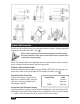
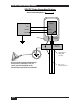
Perform set point adjustment per previous
instructions.
Move the process level above the setpoint.
Turn the adjustment on the AD (adjustable
differential) circuit board fully counterclockwise.
Move the process level to the point where
the control will change state.
Turn the adjustment on the AD circuit board
clockwise carefully until green and yellow
LED’s exchange states.