
Instruction Manual

8/16
Form 925 (08.13) ©SOR Inc.
Sensor Monitor Calibration (with probe attached)
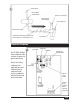
Remove the housing cover.
Verify there is no process material on the probe.
Turn ALARM adjustment counterclockwise until the red LED just lights. At this point,
the loop current is stable at 25.5 mA +1.5 mA. Turn the adjustment clockwise until the
red LED turns off. Turn ALARM adjustment 1/2 turn further clockwise. At this point, the
loop current is stable at 7.5 mA ± 1.5 mA or 14.5 mA ± 2 mA.
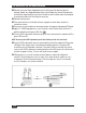
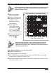
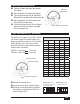
Current Output
Green LED
(7.5 mA)
Yellow LED
(14.5 mA)
Red LED
(25.5 mA)
Current
Meter
(+/-1.5A)
Sensor
Status
Failsafe
Switch
Position
off on off 14.5 mA Wet LO
on off off 7.5 mA Dry LO
on off off 7.5 mA Wet HI
off on off 14.5 mA Dry HI
off on on 25/5 mA Failure LO/HI
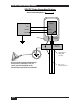
Set Point Calibration
If the delay timer board is present (DT accessory), move all switches to “off” position.
If the adjustable differential board is present (AD accessory), turn the adjustment fully
clockwise.
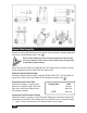
Determine the desired FAILSAFE SELECT switch position for your application by using
the Current Output Chart. (See
).
Failsafe LO Calibration
Move FAILSAFE SELECT switch on the control board to the LO position.
Move the process level to the point where switching is needed.
Turn the LEVEL adjustment so that the yellow LED just lights and the green LED is off.
At this point, the loop current is stable at 14.5 mA ± 2 mA.
Lower the process level until the green LED lights, and the yellow LED is off. At this
point, the loop current is stable at 7.5 mA ±1.5 mA.
Failsafe HI Calibration
Move FAILSAFE SELECT switch on the control board to the HI position.
Move the process level to the point where switching is needed.
Turn the LEVEL adjustment so that the green LED lights, and the yellow LED is off. At
this point, the loop current is stable at 7.5 mA ±1.5 mA.
Lower the process level until the yellow LED lights, and the green LED is off. At this
point, the loop current is stable at 14.5 mA ± 2 mA.