
Instruction Manual

Form 925 (08.13) ©SOR Inc.
7/16
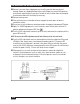
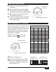
Sensor Monitor and Set Point Calibration
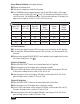
Loop Resistance vs. Power Supply Voltage
Power Supply Voltage (Volts)
750
700
650
550
500
450
400
350
300
250
200
150
100
50
0
0 5 10 15 20 25 30 35
246 Ohms
at 18 VDC
36 Ohms
at 12 VDC
456 Ohms
at 24 VDC
615 Ohms
at 28 VDC
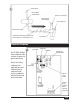
Electical power must be disconnected from explosion proof models before the
cover is removed. Failure to do so could result in severe personal injury or
substantial property damage.
Make sure the power
source is turned off.
Remove the housing cover.
Pull power and signal wires
through the conduit
connection and into the
control housing.
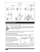
Locate Loop Power
Terminal Block on the
control board. (See
).
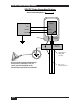
Terminals are labeled “+”
and “-”. Connect power
leads to the proper terminals.
Do not exceed the maximum
loop resistance for the
circuit. (See
).
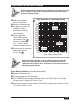
Sensor Monitor Calibration (with probe disconnected)
Remove the housing cover.
Disconnect probe wire from the probe.
Turn ALARM adjustment counterclockwise until the red LED just lights. At this point,
the loop current is stable at 25.5 mA ±1.5 mA.
Reconnect the probe wire to the probe. At this point, the loop current returns to 7.5 mA
± 1.5 mA or 14.5 mA ± 2 mA.
Units in Hazardous Locations – Prior to calibration, make sure that the
work area is declassi ed before removing the explosion proof cover to
calibrate the unit. Failure to do so could result in severe personal injury or
substantial property damage.