
Instruction Manual

Form 925 (08.13) ©SOR Inc.
3/16
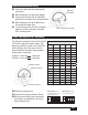
Immerse the sensor in the process material; the green LED should be off. If not, it may
be necessary to decrease the setpoint.
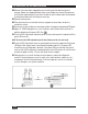
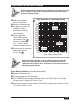
To detect an interface, such as oil/water or foam/liquid, the lighter material must be on
the sensor, then tuned out. Then adjust the setpoint to detect the heavier process \
material. (See
and ).
When the process material has a very low dielectric constant (such as mineral oil and
butane) turn the level adjustment slowly to locate the setpoint, then 1/8 turn to 1/4
turns counterclockwise to precisely set.
When there is a DT in the accessory section of the model number, your level control is
equipped with the optional delay timer. See page 9 for delay timer operation. The delay
timer option may compensate for wave effects or turbulence and free fall time in solids.
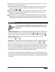
Installation
This product must be installed with an explosion-proof breather vent per
Agency requirements and the National Electric Code-Article 501, Section F,
paragraph 3.
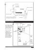
Standard Con guration is a 3/4 NPT(M) pipe nipple that threads into a 3/4” NPT(F) vessel
nozzle or half coupling. Allow a 4-inch turn radius.
(See and
).
Open tanks, vats,
sumps or basins may require a locally made bracket mount similar to that shown
in
.
Optional con guration is a raised face or flat face ANSI flange. See Form 1100 for
selection.
(See and
).
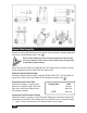
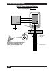
Orientation. The control can be mounted in any position. Sensitivity is optimized when the
greatest surface area of the sensor is parallel to the process level.
(See and
).
Placement and orientation of the sensor in a vessel is frequently determined by available
nozzles. The sensor should be away from fill points to avoid false trips. The insulator bush-
ing on the sensor should protrude a minimum of 1” from the inner wall of the vessel. The
sensor must not touch any metal, nor should conductive process build-up be allowed to
form a bridge between the sensor and a grounded metal tank wall.
If the sensor is a solid rod; it may be cut or bent for clearance or placement. Use a 3-inch
radius should a bend be required. It is permissible to increase the sensor length by welding
a length of identical rod to the supplied sensor. Recalibration is required if the probe length
is changed.