
Instruction Manual

2/16
Form 925 (08.13) ©SOR Inc.
Pre-Installation I/O Test and Calibration
Remove instrument from shipping box and visually inspect for obvious physical
damage. Report any shipping damage to the carrier. Report any internal discrepancies
to the factory representative in your area. Record the serial number from the nameplate
should conversation with the factory be necessary.
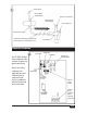
Remove housing cover.
Place instrument on an insulated surface or support so sensor does not touch a
conductive surface.
Ensure area is safe and observe normal precautions for exposed and powered PC board.
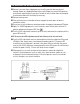
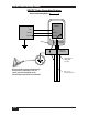
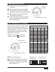
Apply 12 - 28VDC loop power to + and - terminals, move failsafe select switch to LO
position and observe the green LED. (See
).
Turn the LEVEL adjustment clockwise (up to 25 turns) to decrease the setpoint until the
green LED turns off.
NOTE: Do not turn the LEVEL adjustment past 25 turns! Damage to the unit could result.
Turn the LEVEL adjustment one turn counterclockwise from the setpoint until the green
LED lights. Next, slowly move a hand toward the probe to touch it. The green LED
should stay on until the probe is touched. If the green LED turns off when the hand is
near, turn the LEVEL adjustment counterclockwise so the LED remains lit until the hand
touches the probe. Usually, 1-2 turns will locate the new setpoint.
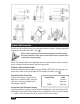
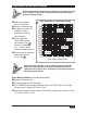
When practical, use a small container of actual process material to calibrate the
control. If the actual process vessel is metal, use a metal container (coffee can, etc.)
and ground it to the instrument housing. If the actual process vessel is an insulator,
such as, fiberglass, use a plastic container.
Oil
Water