
Instruction Manual

10/16
Form 925 (08.13) ©SOR Inc.
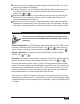
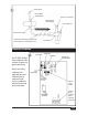
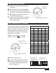
Disconnect power to the unit.
Remove the housing cover.
Remove two screws holding bracket to plastic holder.
Slide out PC board to expose the sensor connection.
Disconnect the sensor wire.
Unscrew the sensor from the housing.
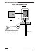
Apply thread sealant to the male threads of the new sensor.
Thread the new sensor into the bottom of the housing.
Connect the sensor wire to the “probe” connection on the circuit board.
Slide the PC board into the grooves in the plastic ring inside the housing.
Replace the two screws holding the bracket to the plastic holder. These screws are self-
tapping. Do not over–tighten.
Reconnect power and replace the housing cover.
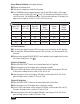
Replacement Sensors
See Form 1100 RF Catalog for replacement sensor model numbers
Sensor Replacement
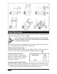
Circuit Board Replacement
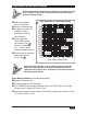
Disconnect power to the unit.
Remove the housing cover.
Remove the two screws holding the bracket to the plastic holder.
Slide out PC board.
Disconnect power wiring, sensor wire, and the ground connection to the housing.
Connect the power wiring and sensor lead to the new board. Connect ground to the
housing.
Slide the new board into the control housing.
Replace the two screws holding the bracket to the plastic holder. These screws are
self-tapping. Do not over–tighten.
Reconnect power and replace the housing cover.