660 Multipoint Electronic Level Switch General Instructions The Multipoint Electronic Level Switch is a level sensing device which reads process level by capacitance measurement. Capacitance varies according to the height of the process inside the vessel. Capacitance variation in the circuit is electronically monitored, and DPDT relay contacts change state at user selected set points to signal process presence at specific process levels.
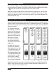
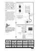
Sensing Level Configuration The number of set points and their configuration depends upon the model number specified for manufacture. Compare the first three numbers from the nameplate model number to to find the sensing level configuration for the unit to be installed. Models 661 through 664 provide fixed, narrow differential set points only. For each fixed differential set point, relay operation is centered on a single point.
Set up Review Probe set up overview and considerations on page 6 to determine the best approach to set up. Two set up methods are possible. Actual Level set up begins in the right column on page 8. Calculated Level set up begins in the left column on page 9. Review both methods. Actual Level set up is preferred, but may not be practical for all installations. Probe Installation All models Probes are mounted vertically from the top of a vessel.
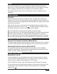
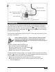
Connect the shield to GND on the set point adjustment board and on the probe adjustment board. Connect the +12 terminal on the set point adjustment board to the +12 terminal on the probe adjustment board. Connect the SIG terminal on the set point adjustment board to the SIG terminal on the probe adjustment board. (See detail.) Model 66J 3/4” NPT(F) Conduit Connections Electrical power must be disconnected from explosion proof models before the cover is removed.
The housing and the PC Board must be connected to ground. Ground (earth) screws are provided on the three-position PC board terminal strip and on the housing floor. Control Cable connection is detailed later in these instructions, after probe set up and set point adjustment. GND SIG +12 Terminal Connection Detail Shield GND SIG +12 Make sure that field power matches the instrument’s power requirements. The fifth place designator in the nameplate model number specifies power ) Make requirement.
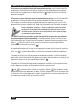
Probe Set up Overview and Considerations If the process can easily be raised and lowered during set up, use the Actual Level Set up procedure. During Actual Level Set up, the process must be positioned to maximum level and to each set point level as briefly outlined in . Begin the Actual Level Set up procedure on page 8. If the process cannot easily be raised and lowered during set up, use the Calculated Set up procedure. During Calculated Set up, picofarad readings are taken at two levels.
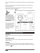
Probe Tip Termination Notes For sheath probes, the last inch of the rigid probe is inactive. The flexible probes terminate with inactive 316SS weights. The weights are insulated from the probe, and 3/4-16 UNF threads are provided for connection to locally provided anchoring hardware. Maximum level Probe Span Set points can be positioned anywhere within span without resetting probe span Form 677 (05.13) ©SOR Inc. Step 1 At maximum level adjust probe span.
Actual Level Set up For Actual Level Set up, the process must be positioned to maximum level to set the probe span. The process is then lowered to each set point in turn, and at each stop the appropriate set point threshold is adjusted. Units in Hazardous Locations — Prior to calibration, make sure that the work area is declassified before removing the explosion proof cover to calibrate the unit. Failure to do so could result in severe personal injury or substantial property damage.
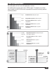
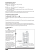
Probe lead Off (open) position GND wire (shield drain) Range selection DIP switches (On/closed position) Probe loading LED Probe span pot Calculated Set up For Calculated set up, the capacitor substitution box is used to determine the picofarad ). Subsequent calculations value of the process at two levels (A & B in the example p to locate adjustments provide the rest of the values required for complete set up. See to locate adjustments when setting up when setting up a remote mounted probe.
Set Threshold for Level A Watch the probe loading LED: LED is on — close DIP switch 1 and go to step 2. LED is off — go to step 3. LED is on — close DIP switches 1 & 2 and go to step 3. LED is off — go to step 3. Turn the span pot CW until the probe loading LED lights, and then CCW to the point where the LED goes off. Slowly cycle the LED on and off as required to find the precise threshold at which the LED goes off. The instrument is now tuned to the picofarad value for Level A.
All Models The capacitor substitution box will inject capacitance, emulating the probe. Using the thumbwheels on the capacitor substitution box, gradually increase the injected capacitance until the probe loading LED lights. Note the value on the substitution box thumb wheels when the probe loading LED lights; record that value on line 4 of the worksheet. The recorded value is the picofarad value for level A (2200 pf on page 12).
Calculated Probe Set up Inject the picofarad equivalent of maximum level from line 11 of the worksheet. Watch the probe loading LED: LED is on — close DIP switch 1 and go to step 2. LED is off — go to step 3. LED is on — close DIP switches 1 & 2 and go to step 3. LED is off — go to step 3. Turn the span pot CW until the probe loading LED lights, and then CCW to the point where the LED goes off. Slowly cycle the LED on and off as required to find the precise threshold at which the LED goes off.
Calculated Set up Vessel Level A . . . . . . .. . .. . .. . .. . . . . . . . . . . . .10 ft. Vessel Level B . . . . . . .. . .. . .. . .. . . . . . . . . . . . . 8 ft. Line 1 - Line 2 . . . . . . .. . .. . .. . .. . . . . . . . 10 - 8 = 2 ft. Capacitance @ Level A. .. . .. . .. . .. . . . . . . . . . . 2200 pf Capacitance @ Level B. .. . .. . .. . .. . . . . . . . . . . 1900 pf Line 4 - Line 5 . . . . . . .. . .. . .. . .. . . 2200 - 1900 = 300 pf Line 6 ÷ Line 3. . . . . . .. . .. . .. . ..
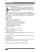
Model 661 Set Point Set up and Output Wiring Adjust Failsafe Hi/Lo ON RELAY FAILSAFE LEVEL LEVEL TIME DELAY RELAY FAILSAFE RANGE SET POINT #4 ON Set Point 1 Terminals OFF RELAY FAILSAFE OFF *When the time delay option is not specified: TIME DELAY ON SET POINT #2 *Off Delay Relay On LED TIME DELAY OFF SET POINT #1 *On Delay LEVEL LEVEL TIME DELAY *Presence LED SET POINT #3 Set Point 1 OFF ON RELAY FAILSAFE SPAN Relay On LED functions as Presence LED Starred parts not suppl
Output Relay Wiring Before connecting the output relay to external devices, determine which failsafe mode is best suited for the sensing level. Refer to the continuity chart to the right when connecting to the relay terminal strip. LO mode: When the set point is satisfied, the relay turns on. When process level falls below the set point, the relay turns off and remains off until the set pint is once again satisfied. HI mode: When the set point is satisfied, the relay turns off.
Model 662 Set Point Set up and Output Wiring Failsafe Hi/Lo TIME DELAY OFF ON RELAY FAILSAFE RELAY FAILSAFE LEVEL LEVEL TIME DELAY ON SET POINT #4 OFF *When the time delay option is not specified: SET POINT #2 ON Relay On LED TIME DELAY OFF SET POINT #1 On Delay* Off Delay* LEVEL LEVEL RELAY FAILSAFE RANGE TIME DELAY Adjust Presence LED* SET POINT #3 Set Point 1 Adjust Presence LED* On Delay* Off Delay* Relay On LED Set Point 1 Set Point 2 Terminals Set Point 1 Terminals Fails
Output Relay Wiring Before connecting output relays to external devices, determine which failsafe mode is best suited for each sensing level. Refer to the continuity chart below when connecting to relay terminal strips. LO mode: When the set point is satisfied, the relay turns on. When process level falls below the set point, the relay turns off and remains off until the set point is once again satisfied. HI mode: When the set point is satisfied, the relay turns off.
Model 663 Set Point Set up and Output Wiring SET POINT #2 TIME DELAY ON RELAY FAILSAFE LEVEL LEVEL OFF ON TIME DELAY Relay On LED functions as Presence LED Starred parts not supplied OFF RELAY FAILSAFE SET POINT #4 *When the time delay option is not specified: ON TIME DELAY Failsafe Hi/Lo OFF SET POINT #1 On Delay* Off Delay* Relay On LED LEVEL LEVEL RELAY FAILSAFE RANGE TIME DELAY Adjust Presence LED* SET POINT #3 Set Point 1 OFF ON RELAY FAILSAFE SPAN Adjust Presence LED* O
Output Relay Wiring Before connecting output relays to external devices, determine which failsafe mode is best suited for each sensing level. Refer to the continuity chart below when connecting to relay terminal strips. LO mode: When the set point is satisfied, the relay turns on. When process level falls below the set point, the relay turns off and remains off until the set point is once again satisfied. HI mode: When the set point is satisfied, the relay turns off.
Model 664 Set Point Set up and Output Wiring Set Point 4 TIME DELAY SET POINT #2 ON OFF ON RELAY RELAY FAILSAFE FAILSAFE LEVEL LEVEL OFF ON SET POINT #4 TIME DELAY Adjust Presence LED* On Delay* Off Delay* Relay On LED Failsafe Hi/Lo OFF LEVEL RELAY FAILSAFE RANGE TIME DELAY On Delay* Off Delay* Relay On LED Failsafe Hi/Lo LEVEL SET POINT #1 TIME DELAY Adjust Presence LED* SET POINT #3 Set Point 1 OFF ON RELAY FAILSAFE SPAN Adjust Presence LED* On Delay* Off Delay* Relay On LED Failsafe
Output Relay Wiring Before connecting output relays to external devices, determine which failsafe mode is best suited for each sensing level. Refer to the continuity chart below when connecting to relay terminal strips. LO mode: When the set point is satisfied, the relay turns on. When process level falls below the set point, the relay turns off and remains off until the set point is once again satisfied. HI mode: When the set point is satisfied, the relay turns off.
Model 665 Set Point Set up and Output Wiring ADJUSTABLE DIFFERENTIAL SET POINT UPPER LIMIT RANGE Upper Limit Adjust Presence LED for Upper Relay On LED RELAY FAIL SAFE LOWER LIMIT Adj Diff Set Point 2 Adj. Diff Failsafe Hi/Lo Lower Limit Adjust Presence LED for Lower SPAN *When the time delay option is not specified: Relay On LED functions as Presence LED Starred parts not supplied Actual Level set point set up Continued from page 8.
Output Relay Wiring Before connecting the output relay to external devices, determine which failsafe mode is best suited for the adjustable differential set point. Refer to the continuity chart below when connecting to the adjustable differential relay terminal strips. For the adjustable differential set point: LO mode: When the upper limit is satisfied, the relay turns on. When process level falls below the lower limit, the relay turns off and remains off until the set point is once again satisfied.
Model 666 Set Point Set up and Output Wiring Upper Limit Adjust *Presence LED ON TIME DELAY OFF SET POINT #1 *On Delay *Off Delay Relay On LED Failsafe Hi/Lo *When the time delay option is not specified: Relay On LED functions as Presence LED Starred parts not supplied RANGE UPPER LIMIT ADJUSTABLE DIFFERENTIAL SET POINT Set Point 1 Upper Limit Adjust Presence LED for Upper Limit Relay On LED RELAY FAIL SAFE LOWER LIMIT Set Point 2 Adj.
For set point 1: LO mode: When the set point is satisfied, the relay turns on. When process level falls below the set point, the relay turns off and remains off until the set point is once again satisfied. HI mode: When the set point is satisfied, the relay turns off. When process level falls below the set point, the relay turns on and remains on until set point is once again satisfied. For the adjustable differential set point: LO mode: When the upper limit is satisfied, the relay turns on.
Model 667 Set Point Set up and Output Wiring Actual Level set point set up Continued from page 8. Process level must be steady at the upper limit of the adjustable differential set point. Turn upper limit (pump up) adjust pot CW until its Presence LED lights and then CCW to the point where the LED goes off. Slowly cycle the Presence LED on and off as required to find the precise threshold at which the LED goes off. Lower process level to lower limit of the adjustable differential set point.
For set point 4: LO mode: When the set point is satisfied, the relay turns on. When process level falls below the set point, the relay turns off and remains off until the set point is once again satisfied. HI mode: When the set point is satisfied, the relay turns off. When process level falls below the set point, the relay turns on and remains on until set point is once again satisfied. For the adjustable differential set point: LO mode: When the upper limit is satisfied, the relay turns on.
Set Point 1 Adjust *Presence LED *On Delay *Off Delay Relay On LED Fail-safe Hi/Lo Set Point 4 LEVEL OFF ON TIME DELAY Adjust *Presence LED *On Delay *Off Delay Relay On LED Fail-safe Hi/Lo ADJUSTABLE DIFFERENTIAL SET POINT Model 668 Set Point Set up and Output Wiring RELAY FAIL SAFE RANGE UPPER LIMIT RELAY FAIL SAFE LOWER LIMIT Upper Limit Presence LED for Upper Limit Relay ON LED Set Point 2 Adj.
Output Relay Wiring Before connecting output relays to external devices, determine which failsafe mode is best suited for each sensing level. Refer to the continuity chart below when connecting to relay terminal strips. For set point 1 & 4: LO mode: When the set point is satisfied, the relay turns on. When process level falls below the set point, the relay turns off and remains off until the set point is once again satisfied. HI mode: When the set point is satisfied, the relay turns off.
SOR RF Probe Grounding Scheme Critical Grounding Path = Power Supply Line Circuit Board Line Neutral Neutral Ground Ground Electronics Housing Process Connection IMPORTANT! Do not provide separate earth grounding for the process connection. This can create a parallel grounding circuit that will impair operation and callibration. SOR Supplied Stilling Well (optional) Probe Center Conductive Element 30/36 Form 677 (05.13) ©SOR Inc.
Control Drawing Form 677 (05.13) ©SOR Inc.
Control Drawing 32/36 Form 677 (05.13) ©SOR Inc.
Dimensions - W Housing Configuration Dimensions are for reference only. Contact the factory for certified drawings for a particular model number. Linear = mm/inches Drawing 0390655 Form 677 (05.13) ©SOR Inc.
Dimensions - J Housing Configuration (Explosion Proof Integral) 180.9 7.12 101.6 4.00 1 Dimensions are for reference only. Contact the factory for certified drawings for a particular model number. C ELECTRICAL CONNECTION 1 NPT (F) STANDARD 3/4 NPT (F) OPTIONAL PROCESS CONNECTION (SEE TABLE) 1 B INACTIVE SHEATH LENGTH (PER MODEL NUMBER) A LENGTH (PER MODEL NUMBER) 19.1 0.75 (INACTIVE SHEATH ONLY) D NOTES: 1. THESE DIMENSION ARE BASED UPON A 5 THREAD ENGAGEMENT.
Dimensions - R Housing Confirmation (Explosion-Proof Remote) Dimensions are for reference only. Contact the factory for certified drawings for a particular model number. 1 NPTF STANDARD 3/4 NPTF OPTIONAL ELECTRICAL CONNECTION 3/4 NPTF ELECTRICAL CONNECTION ELECTRONICS HOUSING 118.6 4.67 96.0 3.78 3/4 NPTF ELECTRICAL CONNECTION 1 C PROCESS CONNECTION SEE TABLE B 1 INACTIVE SHEATH LENGTH PER MODEL NUMBER 19.1 0.
Dimensions - Other Sensors Dimensions are for reference only. Contact the factory for certified drawings for a particular model number. 3/4-16 UNF-2B DUAL RIGID PROBE DETAIL 31.8 1.25 28.4 1.12 50.8 2.00 MINIMUM CLEARANCE HOLE FOR INSTALLATION 54.9 2.16 SEE DETAIL A 31.8 1.25 27.0 1.06 54.0 2.13 DUAL CABLE PROBE DETAIL D 11.1 0.44 3/4-16 UNF-2B 36.5 1.44 22.2 0.88 Linear = mm/inches Drawing 0390657 Printed in USA www.sorinc.