
Instruction Manual

Form 416 (01.13) ©SOR Inc.
1/8
These instructions provide information for installation and
field calibration of B Temperature Switches.
Process temperature changes cause proportional
vapor pressure changes in the temperature sensing
bulb that acts on a diaphragm/piston assembly to
actuate and deactuate a snap-action electrical switching
element at discrete process temperatures. The instrument’s
behavior is determined by vapor pressure (105 range model
fill media is inert gas). For best results with the SOR
®
thermal activated temperature switch, the entire probe
must experience the media being monitored. If a
thermowell is being used, a thermal paste is recommended
to ensure the transfer of heat through the well to the probe.
B Temperature Switches
General Instructions
Registered Quality System to ISO 9001
Design and
specifications are
subject to change
without notice.
For latest revision, go to
www.sorinc.com
Table of Contents
Installation ....................................... 2
SIL Installation ..................................2
Electrical Connection ...........................3
Calibration .......................................3
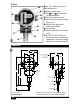
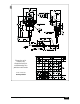
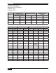
Dimensions ......................................4
Operation.........................................6
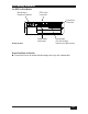
ATEX Marking Information .....................7
Declaration of Conformity .....................8
n
and
i
n
g
ment’s
e
model
®
b
e
m
ended
probe
.
NOTE: If you suspect that a product is defective, contact the factory
or the SOR Representative in your area for a return authorization
number (RMA). This product should only be installed by trained
and competent personnel.