3-776-792-12(1) Remote Control Panel Operating Instructions Before operating the unit, please read this manual thoroughly and retain it for future reference.
WARNING To prevent fire or shock hazard, do not expose the unit to rain or moisture. To avoid electrical shock, do not open the cabinet. Refer servicing to qualified personnel only. AVERTISSEMENT Afin d’éviter tout risque d’incendie ou d’électrocution, ne pas exposer cet appareil à la pluie ou à l’humidité. Afin d’écarter tout risque d’électrocution, garder le coffret fermé. Ne confier l’entretien de l’appareil qu’à un personnel qualifié.
Table of Contents Overview ............................................................................ 4 Features ............................................................................... 4 Locations and Functions of Parts ................................... 5 Operation Panel ................................................................... 5 Connector Panel ................................................................ 13 Mounting on a Console ..................................................
Overview The RCP-D50/D51 Remote Control Panel enables remote operation of the DXC-D50-series, DXC-D30/ D35-series,or DXC-637-series Color Video Cameras. The RCP-D50 and RCP-D51 are completely identical in their functions except with respect to the iris and master black adjustments. For the iris and master black adjustments, the RCPD50 uses a joystick type control while the RCP-D51 uses rotary knobs.
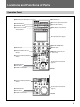
Locations and Functions of Parts Operation Panel 1 MASTER and SLAVE buttons 2 PREVIEW button 3 STANDARD button 4 Camera/CCU function ON/OFF buttons qa ASSIGN button MASTER SLAVE ASSIGN CAM PW BARS CLOSE WHITE BLACK qs Power and output select buttons AUTO SETUP qd AUTO SETUP buttons PREVIEW SKIN DTL LEVEL START STANDARD SET UP qf White balance control buttons 5600K AUTO KNEE SKIN DETAIL PRESET A WHITE DETAIL GATE PAINT1 PAINT2 PAINT3 SCENE OTHERS FUNCTION MONITOR MENU B Menu operation bl
Locations and Functions of Parts 1 MASTER and SLAVE buttons When adjusting the white balance of multiple cameras in Master/Slave mode, designate the master camera or the slave cameras. Press and light up the MASTER button to specify the connected camera for the master. Press and light up the SLAVE button to specify the connected camera for the slave. The slave cameras follow the master camera settings. If you press a button when lit, it goes dark.
0 PANEL ACTIVE button Press and light up the button to permit this panel to control the camera system (Panel active status). The IRIS/M.BLACK ACTIVE button of the iris/ master black control block also lights. If you press this button so that it goes dark, the panel will be locked, preventing accidental misoperation. If Panel Active Lock with a security code has been enabled, the PANEL ACTIVE and the IRIS/ M.
Locations and Functions of Parts qf White balance control buttons PRESET A WHITE B PRESET: Press and light this button to retrieve the preset white balance of the camera. A (memory A): Press and light this button to retrieve the white balance stored in memory A of the camera. B (memory B) (valid only with the DXC-D50 series): Press and light this button to retrieve the white balance stored in memory B of the camera.
Menu operation block 2 1 PAINT 1 PAINT 2 PAINT 3 SCENE OTHERS FUNCTION MONITOR MENU 3 MONITOR BRIGHT CONTRAST 4 1 MENU buttons Select the menu mode. If you press and light one of these buttons, the menu for the selected mode appears on the LCD. PAINT 1/2/3: Each selects the Paint menu to adjust various paint items, such as white, black, and flare. The configuration of the Paint menu depends on the connected camera.
Locations and Functions of Parts Iris/master black control block (RCP-D50) 3 IRIS/M.BLACK LINK button 4 IRIS/M.BLACK ACTIVE button 5 AUTO button 6 f-number display 7 EXT indicator EXT IRIS/M.BLACK ACTIVE IRIS/M.
5 AUTO button Press and light the button to automatically adjust the iris according to the amount of input light. When this button is lit, the reference value for automatic iris adjustment can be set with the iris control. If you press the button when lit, it goes dark and manual iris adjustment is enabled. 6 f-number display Displays the f number of the current iris setting. When the iris is closed, “CL” is displayed. When the DXC-D50 series is connected, “OP” is displayed for the maximum f-number value.
Locations and Functions of Parts Iris/master black control block (RCP-D51) 4 IRIS RELATIVE button 5 IRIS/M.BLACK LINK button 1 MASTER BLACK display 6 f-number display EXT 7 EXT indicator 2 MASTER BLACK control 8 SENS control knob MASTER BLACK 9 COARSE control knob RELATIVE IRIS/ M.BLACK LINK SENS CLOSE OPEN COARSE 3 IRIS/M.BLACK ACTIVE button AUTO IRIS/M.
8 SENS (sensitivity) control knob Used for manual iris adjustment in Absolute mode. This control is not operative when Relative mode is selected. Connector Panel 1 MONITOR connector See the table “Iris adjustment functions”on page 11. 2 CCU/CAMERA connector 9 COARSE control knob Used for manual iris adjustment. 3 EXT I/O connector MONITOR See the table “Iris adjustment functions” on page 11. 0 IRIS control When the AUTO button is not lit, you can adjust the iris manually by turning the control.
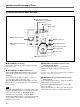
Mounting on a Console The RCP-D50/D51 can be mounted on a console as shown below: 14
Menu Configuration and Basic Menu Operations The RCP-D50/D51 provides menu operations for various functions such as adjustments of system equipment. When the selected menu is composed of multiple pages With the menu that is composed of multiple pages such as Paint menu, press v or V to flip the pages. See “Initial display (Paint menu)” on the next page. Basic Operating Procedure When a submenu is shown Press the desired submenu item to change the display. 1 See “Submenu” on page 17.
Menu Configuration and Basic Menu Operations Basic Configuration of Menu Display Status display When you do not select any menu or the signal from the camera, the LCD shows the following status display: On the status display, the set value of each item is only displayed. The setting is made with the Function menu or with the corresponding knob on the operation panel. Status Shutter 60 When you select a scene file, the filename is displayed. The set values of the shutter and master gain are displayed.
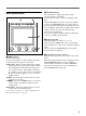
Adjustment display (Paint menu) When you select an item on the initial display of the Paint menu, the lower half of the panel becomes the adjustment display for the selected item. Example: when you select “White” from the PAINT 1 initial display with the DXC-D50 series connected Clear When you press this, the upper half of the panel becomes the monitor output setting display (see page 19).
Menu Configuration and Basic Menu Operations Function menu displays When you press and light the FUNCTION button of the menu operation block, the scene file operation menu display is obtained. When “Operation” is selected Example: with the DXC-D50 series connected Operation Press one of these buttons calls the adjustment display of the corresponding paint item. The items to be displayed on this Function menu can be changed using the OTHERS menu.
Monitor output set display (Expansion menu) When you press [Monitor Select] on an adjustment display of the Paint menu, the upper half of the panel becomes the monitor output setting display. When the CCU-TX7 is connected, you can select the WF/PIX output signals. R/G/B: To independently select the R, G, or B signal. RGB: To select the R, G, and B signals in combination. SEQ: Only the WF output is enabled, and you can monitor the waveforms of the R, G, and B signals in sequence.
Menu Configuration and Basic Menu Operations Menu Items with the DXC-D50-Series Cameras The “Control items” marked with z are those assigned to the control knobs. The other items are operated on the menu display. The items displayed differ according to whether the unit is in Advanced Setting mode or in Normal Setting ) in the table below are mode. The items shaded ( displayed only in Advanced Setting mode.
Page Menu Submenu Control item Function Paint 2 Detail Detail 1 • Level To adjust the detail (contour correction) level • H/V Ratio To adjust the ratio of V (Vertical) detail to H (Horizontal) detail in detail correction. As the value becomes larger, the V detail ratio increases.
Menu Configuration and Basic Menu Operations Page Menu Paint 4 White Clip TLCS Auto Iris CLS/EVS Paint 5 22 Submenu Control item Function • Master To adjust the amount of white clip (the highest white level). As the value becomes larger, the output level decreases. TLCS To turn the TLCS (total level control) function ON/OFF • AGC/C.Point To set the f-stop value (f-2, f-2.8, f-4, or f-5.
Function menu (with the DXC-D50 series) Menu Control item Function Operation Jump menu 1 To jump to the adjustment screen designated for Menu 1 in Menu Set a)(Default: White of Paint 1) Jump menu 2 To jump to the adjustment screen designated for Menu 2 in Menu Set a) (Default:Black of Paint 1) Jump menu 3 To jump to the adjustment screen designated for Menu 3 in Menu Set a) (Default: Flare of Paint 1) Jump menu 4 To jump to the adjustment screen designated for Menu 4 in Menu Set a) (Default: Gamm
Menu Configuration and Basic Menu Operations OTHERS menu (with the DXC-D50 series) Menu 2ndary menu Submenu Control item Function Adjusting White Shading •R To adjust the V white shading (vertical variation of the white) of the R signal •G To adjust the V white shading of the G signal Camera Config Camera ID Center Marker File •B To adjust the V white shading of the B signal CAM ID IND To turn the camera ID display ON/OFF while the camera is in Color Bars mode Clock IND Switching of the
Menu 2ndary menu Submenu RCP Config VR Setting (cont.) (cont.) Control item Function M.
Menu Configuration and Basic Menu Operations Menu 2ndary menu Submenu RCP Config Security (cont.) Control item Engineer Mode Status a) To set whether to display “Status”, “Menu Set”, and “Code No.” or not (With Engineer Mode ON, all operative menu items are displayed regardless of the Advance Mode setting.
Menu Items with the DXC-D30/D35-Series Cameras The “Control items” marked with z are those assigned to the control knobs. The other items are operated on the menu display. The items displayed differ according to whether the unit is in Advanced Setting mode or in Normal Setting ) in the table below are mode. The items shaded ( displayed only in Advanced Setting mode. Switching between Normal Setting mode and Advanced Setting mode is performed in RCP Config (Security → Status) on the OTHERS menu.
Menu Configuration and Basic Menu Operations Page Menu Submenu Control item Function Paint 2 Detail Detail 1 • Level To adjust the detail (contour correction) level • H/V Ratio To adjust the ratio of V (vertical) detail to H (horizontal) detail in detail correction. As the value becomes larger, the V detail ratio increases.
Page Menu Paint 2 Black STR (cont.
Menu Configuration and Basic Menu Operations Page Menu Submenu Paint 4 CLS/EVS (cont.
Menu Lens/Pan Submenu Control item a) Function Option 1 To turn the option control function 1 ON/OFF Option 2 To turn the option control function 2 ON/OFF • Focus b) To adjust the focus b) To adjust the zoom • Zoom • Pan c) • Tilt c) To adjust panning of the tripod head To adjust tilting of the tripod head a) The item “Lens/Pan” is displayed when Pan/Tilt Enable is set to ON with Security of RCP Config on the OTHERS menu.
Menu Configuration and Basic Menu Operations Menu 2ndary menu Submenu RCP Config RCP (cont.) Adjusting (cont.
Menu 2ndary menu Submenu RCP Config Security (cont.) Control item Engineer Mode Status a) To set whether to display “Status”, “Menu Set”, and “Code No.” or not (With Engineer Mode ON, all operative menu items are displayed regardless of the Advance Mode setting.
Menu Configuration and Basic Menu Operations Menu Items with the DXC-637-Series Cameras The “Control items” marked with z are those assigned to the control knobs. The other items are operated on the menu display. To operate the DXC-637-series cameras from this unit, it is necessary to connect the camera and this unit via the CCU-TX7. The items displayed differ according to whether the unit is in Advanced Setting mode or in Normal Setting ) in the table below are mode.
Function menu (with the DXC-637 series) Menu Control item Function Operation Jump menu 1 To jump to the adjustment screen designated for Menu 1 in Menu Set a)(Default: White of Paint 1) Jump menu 2 To jump to the adjustment screen designated for Menu 2 in Menu Set a) (Default:Black of Paint 1) Jump menu 3 To jump to the adjustment screen designated for Menu 3 in Menu Set a) (Default: Flare of Paint 1) Jump menu 4 To jump to the adjustment screen designated for Menu 4 in Menu Set a) (Default: Gamm
Menu Configuration and Basic Menu Operations OTHERS menu (with the DXC-637 series) Menu 2ndary menu Submenu Control item Function Camera Config Title ID Title IND To turn the title display ON/OFF while the camera is in Color Bars mode Clock IND Switching of the clock indication Cam: To always display the clock indication Off: No clock indication File Copy to Slave RCP Config RCP Adjusting To copy the status of the master unit to slave units Buzzer • Call To set the volume of the call buzzer
Menu 2ndary menu Submenu RCP Config Comm Link (cont.
Menu Configuration and Basic Menu Operations Menu Items with the CCU-TX50 The “Control items” marked with z are those assigned to the control knobs. The other items are operated on the menu display. The items displayed differ according to whether the unit is in Advanced Setting mode or in Normal Setting ) in the table below are mode. The items shaded ( displayed only in Advanced Setting mode.
Page Menu Submenu Control item Function Paint 2 Detail Detail 1 • Level To adjust the detail (contour correction) level • H/V Ratio To adjust the ratio of V (Vertical) detail to H (Horizontal) detail in detail correction. As the value becomes larger, the V detail ratio increases.
Menu Configuration and Basic Menu Operations Page Menu Paint 4 White Clip TLCS Auto Iris CLS/EVS Paint 5 40 Submenu Control item Function • Master To adjust the amount of white clip (the highest white level). As the value becomes larger, the output level decreases. TLCS To turn the TLCS (total level control) function ON/OFF • AGC/C.Point To set the f-stop value (f-2, f-2.8, f-4, or f-5.
Function menu (with the CCU-TX50) Menu Control item Function Operation Jump menu 1 To jump to the adjustment screen designated for Menu 1 in Menu Set a)(Default: White of Paint 1) Jump menu 2 To jump to the adjustment screen designated for Menu 2 in Menu Set a) (Default:Black of Paint 1) Jump menu 3 To jump to the adjustment screen designated for Menu 3 in Menu Set a) (Default: Flare of Paint 1) Jump menu 4 To jump to the adjustment screen designated for Menu 4 in Menu Set a) (Default: Gamma/Knee
Menu Configuration and Basic Menu Operations OTHERS menu (with the CCU-TX50) Menu 2ndary menu Submenu Control item Function Adjusting White Shading •R To adjust the V white shading (vertical variation of the white) of the R signal •G To adjust the V white shading of the G signal Camera Config Screen Mode a) File Scene Trans RCP Config RCP Adjusting •B To adjust the V white shading of the B signal Screen Mode To select the Screen mode (4:3/16:9) CAM->MS To transfer a scene file (from the
Menu 2ndary menu Submenu RCP Config Date/Time (cont.) Set Date Control item Function • Year Date adjustment of the clock built into the unit • Month • Day Set Cancel Time • Hour Time adjustment of the clock built into the unit • Minute • Second Set Cancel Protocol Type a) Comm Type Security Engineer Mode Status b) To set whether to display “Status”, “Menu Set”, and “Code No.” or not (With Engineer Mode ON, all operative menu items are displayed regardless of the Advance Mode setting.
Menu Configuration and Basic Menu Operations Menu 2ndary menu Submenu Control item Function LCD (cont.) LCD Brightness/Contrast • Bright To set the brightness of the LCD of the unit LCD Moni.
Initial Settings Setting the Operating Conditions of the RCP-D50/D51 RCP Config. Menu By using the RCP Config menu or LCD setting display, you can set the built-in clock of the RCP-D50/ D51 and adjust various conditions of the RCP-D50/ D51, such as the sound volume of the warning buzzer and the brightness of the indicators and LCD. RCP Adjusting RE Setting Cable Comp SW Setting Camera No. Exit Date Time Security To obtain the LCD setting display, press [LCD].
Initial Settings 4 To set the date: Adjusting the Buzzer Sound 1) Press and light [Date]. Date Time Setting Exit 2001/11/17 (Sat) 22 : 12 : 31 Date Time Year Month 2001 Set Cancel A buzzer sounds on the RCP-D50/D51 when it receives call signal or a panel control is operated. When required, you may turn on/off the buzzer or adjust the sound volume. To adjust the buzzer, proceed as follows: 1 Day 8 Press [RCP Adjusting] on the RCP Config menu. The RCP adjustment menu appears.
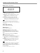
To turn on/off the buzzers independently Press the corresponding button. When it is lit, the buzzer is on. [Call Buzzer]: For the buzzer sound when a call signal is received [Touch Click]: For the buzzer sound when a button displayed on the menu display is operated [SW Click]: For the buzzer sound when a button on the panel is operated lamps, including the master black indicator and f-number indicator The master brightness can be adjusted with the rightmost control knob (Master).
Initial Settings Adjusting the Brightness/ Contrast of the LCD 2 Set the menu to Advanced Setting mode. 1) Press [Security] on the RCP Config menu. 2) Press and highlight [Engineer Mode]. You can adjust the brightness and contrast of the display of the menu control block. Proceed as follows: The [Status], [Menu Set], and [Code No.] buttons are displayed. 3) Press [Status]. 1 Press [LCD] on the OTHERS menu to display the LCD setting display. Clear Exit The Security Status menu appears.
If you enter an incorrect security code, the message “!!!Code No. NG!!!” is displayed. Specifying the Security Codes You can authorize specific persons to set the menu to Engineer mode, to operate this panel, and to adjust the iris and master black by specifying a security code. Locking Engineer mode with a security code 1 2 Press the OTHERS button in the Menu operation block so that the OTHERS menu is displayed on the LCD, then press [RCP Config] to call the RCP Config menu.
Initial Settings The Security Code input display appears. (Pressing [Enable $ENG Code%] registers the same security code as Engineer mode for Panel Active Lock.) 5 Operate in the same manner as step 5 and step 6 in “Locking Engineer mode with a security code.” The Security Status menu is resumed with highlighted [Enable] and additional [Code Change].
File Operations This unit can operate two types of files: scene files and setup files. Setting data of cameras can be registered as scene files or setup files and recalled as required. The table below shows the setting items which can be registered as either of the files.
File Operations Setup file Setting item DXC-D30/D35 series only Gamma correction on/off Master gamma Scene file DXC-D30/D35 series DXC-D50 series yes yes R/B gamma yes yes yes yes Master black gamma yes R/B black gamma yes Gamma initial gain yes yes Black stretch level yes yes Upper/lower limit value for black stretch yes yes Upper/lower limit value for black compress yes DynaLatitude effect yes yes Matrix adjustment ON/OFF Saturation/hue yes yes yes Matrix adjustment mode Ma
If the scene file button corresponding to the memory cell in which you wish to store data is not displayed, press either the v or V button at the lower-right position. You can change the scene file buttons by 5, in the order of [1] to [5], [6] to [10], [11] to [15], and [16] to [20]. You can also change the buttons one by one. When the knob at the leftmost position (Page) is turned clockwise, larger-numbered buttons are displayed one by one.
File Operations Transferring Scene Files between the Camera and a Memory Stick (with the DXC-D50 Series) When a DXC-D50-series camera is connected, the registered scene files can be stored as a data block and can be read when required. Storing the scene files on a Memory Stick Proceed as follows: 1 2 3 Press the OTHERS button in the Menu operation block so that the OTHERS menu is displayed on the LCD, then press [RCP Config] to call the RCP Config menu. Set the menu to Advanced Setting mode.
Operating Setup Files (for DXCD30/D35 Series only) Among the setting items listed in the table on pages 51 and 52, the settings for those items that have “yes” in the Setup-file column are stored as a setup file in the memory of the camera. In addition to five files (PRESET 1 to PRESET 5) that have already been registered in the camera, three more files (USER 1 to USER 3) can be registered and retrieved as required. 5 Press [Store].
Skin Detail Correction/Skin Matrix Adjustment (for DXC-D30/D35/D50 Series Only) The skin detail and skin matrix functions can adjust detail level and matrix (saturation and hue) of a selected skin gate area (area designated by color range). Once a skin gate area has been selected, it can be used as a target for both skin detail correction and skin matrix adjustment, and activation of each function can be performed independently.
Multi-Camera Control Connections and Preparatons In a multi-camera system, connecting all the CCUTX7 units via the RS232C connectors allows one RCP unit selected from all the RCP units in the system to control the multiple cameras. If the selected unit is set as the master unit and the rest are set as slave units, the setting data of the camera connected to the master unit can be transferred to other cameras.
Multi-Camera Control Notes • While scene file transfer is in progress on a slave unit, do not tranfer data from the master unit to the slave unit. Scene file transfer will fail. • The master/slave setting is released while transferring the scene files. Operating Multiple Cameras from One RCP Unit —Command Link Command link allows one RCP selected as the master unit to control the adjustments or settings of the cameras connected to the slave units.
Memory Sticks Using a Memory Stick When a Memory Stick is inserted in the panel, the file data can be stored on the Memory Stick, which enables you to share data among RCPs. Inserting a Memory Stick Insert a Memory Stick with the label side to the left into the Memory Stick slot until it clicks and the access lamp lights in red. Notes on Memory Stick On Memory Stick Memory Stick is a new compact, portable and versatile IC recording medium with a data capacity that exceeds that of a floppy disk.
Memory Sticks Handling of Memory Stick • Image data may be damaged in the following cases: – If you remove the Memory Stick, or turn the power off when the access lamp is lit in red – If you use a Memory Stick near static electricity or a magnetic field We recommend backing up important data. • Prevent metallic objects or your finger from coming into contact with the terminal of the connecting section. • Do not attach any material other than the supplied label to the label space.
Specifications General Power requirements 10.5 to 17 V DC Power consumption 4.5 W Cable length 50 m (164 feet) max. (when the CCA-7 cable is used) Operating temperature 5°C to 40°C (41°F to 104°F) Dimensions (w/h/d) RCP-D50: 102 × 354 × 126.5 mm (4 1/8 × 14 × 5 inches) RCP-D51: 102 × 354 × 86.5 mm (4 1/8 × 14 × 31/2 inches) Mass RCP-D50: 1.5 kg (3 lb 5 oz) RCP-D51: 1.
Sony Corporation