Wall-Mount Bracket Support de fixation murale Soporte de montaje mural Installation Information EN Informations d’installation FR Información para la instalación ES Read this manual before using this product Lisez ce manuel avant d’utiliser le produit Lea este manual antes de usar el producto J-061-100-11(2) SU-WL855
Installation Information for Using Sony Wall-Mount Bracket (SU-WL855) Supported models*1: *1 In the actual model names, the “x”/“xx” indicates numbers and/or characters specific to each model. K-75S3x / 75S3xC / 65XR7x / 65XR7xC / 65S3x / 65S3xC / 55XR7x / 55XR7xC / 55S3x / 55S3xC To Customers For product protection and safety reasons, Sony strongly recommends that installation of your TV or LCD Display be performed by Sony dealers or licensed contractors. Do not attempt to install it yourself.
Wall-Mount Bracket To Customers On Safety Thank you for purchasing this product. To Customers Installing the TV or LCD Display to the Wall WARNING PROFESSIONAL INSTALLATION REQUIRED This product should only be installed by a professional installer who is trained to determine the strength of the wall for withstanding the TV’s or LCD Display's weight. If it is not properly secured during installation, the TV or LCD Display may fall and cause serious injury.
Notice If you use the TV or LCD Display installed on the Wall-Mount Bracket for a long time, the wall behind or above the TV or LCD Display may become discolored or the wallpaper may come unstuck, depending on the material of the wall. If the Wall-Mount Bracket is removed after installing it on the wall, the screw holes are left. Do not use the Wall-Mount Bracket in a place where it is subjected to mechanical vibrations.
Before Getting Started ˎ The TV or LCD Display illustrations shown in this manual are examples used to provide clear explanations of the operations. For this reason, the illustrations may appear different from your actual TV or LCD Display. What Is Your Wall Made Of? Firstly, check the type of the wall to install the TV or LCD Display. The Wall-Mount Bracket differs depending on the type of the wall.
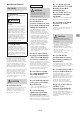
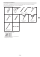
Checking the Parts Supplied with SU-WL855 ˎ Verify that all the parts are included. WM1 (×1) WM2 (×1) WM4 (×1) M6 (×4) WS1 (×4) WS2 (×6) 6 mm × 20 mm (1/4 inch × 13/16 inch) 8 mm × 12 mm (11/32 inch × 1/2 inch) WW1 (×6) WW2 (×4) WT1 (×6) WM3 (×4) Supplied with the TV or LCD Display Wall-Mount Attachment VS (×4)*1 *1 Only for limited region/country/model.
Preparing for Installation ˎ Have the TV’s or LCD Display's Reference Guide and Setup Guide at hand before installation. ˎ Confirm the installing position of your TV or LCD Display. ˎ Prepare the following tools: *1 5.5 mm 10 mm (7/32 inch) (13/32 inch) *2 *3 EN 1.5 N·m/1,5 N·m {15 kgf·cm} 13 mm (1/2 inch) 12.5 N·m/12,5 N·m {130 kgf·cm} *1 Only for dry wall with studs *2 Only for solid concrete or concrete block *3 Depending on models − 7 (EN) − 1.
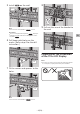
Attaching the Wall-Mount Bracket to the Dry Wall with Studs 2 WM4 3 Align WM4 to the wall and make four marks aligned with the studs. ×4 WM4 WM1 Installing the Lateral Shift Bracket to the Wall 1 Note Decide on the installation location. ˎ Use a level to check whether WM4 is level. Make sure that the wall has enough space for the TV or LCD Display and is capable of supporting a weight of at least six times that of the TV or LCD Display.
5 Install WM4 ×2 8 on the wall. WS2 WW1 WM1 WM4 WS1 9 Note ˎ Use a level to check whether WM4 is level. WW2 Pull out the arm of the bracket to the end. Precaution ˎ Do not over-tighten the lag bolts WS2 . Improper tightening could reduce the holding power of the lag bolts WS2 . 6 EN Drill lower pilot holes on the marks. (Refer step 4 for the drill instruction.
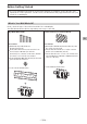
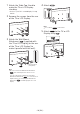
1 4 Attach the Table-Top Stand to make the TV or LCD Display standing. Attach WM3 . WM3 • Refer to your TV’s or LCD Display's Setup Guide. 2 Remove the screws from the rear of the TV or LCD Display. Note ˎ Do not attach WM3 on the labels. 5 3 Attach the Wall-Mount Attachment VS (supplied with the TV or LCD Display) to the rear of the TV or LCD Display (to make it parallel with the wall). Attach WM2 to the TV or LCD Display using M6 . WM2 M6 VS 1.
6 Detach the Table-Top Stand from the TV or LCD Display. The following illustration is an example of the operation. • Remove one side of the Table-Top Stand at a time. Firmly hold the Table-Top Stand securely with both hands while the other people lift up the TV or LCD Display. Installing the TV or LCD Display on the Wall 1 EN • Repeat the previous step and remove the other side of the Table-Top Stand. Note ˎ Three or more people are required to detach the Table-Top Stand.
3 Screw the left and right side of the Wall-Mount Bracket. 5 When moving the TV or LCD Display, hold it firmly from the bottom. M6 Note ˎ The TV or LCD Display may not move near close to the wall depending on the type and number of cables attached. This is not a malfunction. 6 M6 4 WARNING ˎ Two or more persons (three or more persons for 189.3 cm (75 inches) and above TV or LCD Display) are needed to transport a large TV or LCD Display.
Confirming the Completion of the Installation Check the following points. ˎ The cord and the cable are not twisted or pinched. Attaching the Wall-Mount Bracket to the Solid Concrete or Concrete Block WARNING ˎ Improper placement of the AC power cord, etc. may cause fire or electric shock through a short circuit. Be sure to confirm the completion of the installation for safety. Other Information When removing the TV or LCD Display, reverse the previous installation procedure.
2 Align WM1 to the wall and make four marks. 5 Install WM1 on the wall. WM1 ×4 WM1 WS2 WW1 Note ˎ Use a level to check whether WM1 is level. 3 Note Drill pilot holes on the marks. ˎ Use a level to check whether WM1 is level. Make sure the location on the wall to drill the holes are strong enough to support a weight of at least six times that of the TV or LCD Display. Precaution ×4 ˎ Do not over-tighten lag bolts WS2 . Improper tightening could reduce the holding power of lag bolts WS2 .
Note Preparing for the Installation of the TV or LCD Display ˎ Be sure to fasten the Wall-Mount Attachment VS when attaching them to the TV or LCD Display. Use only a flat head screwdriver to install the Wall-Mount Attachment VS . Use of another tool might result in over torqueing the Wall-Mount Attachment VS and damaging the TV or LCD Display. Note ˎ Be sure to store the removed screws and unused parts in a safe place, keeping them away from children. 4 Attach WM3 .
6 Detach the Table-Top Stand from the TV or LCD Display. The following illustration is an example of the operation. • Remove one side of the Table-Top Stand at a time. Firmly hold the Table-Top Stand securely with both hands while the other people lift up the TV or LCD Display. Installing the TV or LCD Display on the Wall 1 • Repeat the previous step and remove the other side of the Table-Top Stand. Note ˎ Three or more people are required to detach the Table-Top Stand.
3 Screw the left and right side of the Wall-Mount Bracket. 5 When moving the TV or LCD Display, hold it firmly from the bottom. M6 Note ˎ The TV or LCD Display may not move near close to the wall depending on the type and number of cables attached. This is not a malfunction. 6 M6 4 WARNING ˎ Two or more persons (three or more persons for 189.3 cm (75 inches) and above TV or LCD Display) are needed to transport a large TV or LCD Display.
Confirming the Completion of the Installation Check the following points. ˎ The cord and the cable are not twisted or pinched. WARNING ˎ Improper placement of the AC power cord, etc. may cause fire or electric shock through a short circuit. Be sure to confirm the completion of the installation for safety. Other Information When removing the TV or LCD Display, reverse the previous installation procedure. WARNING ˎ Two or more persons (three or more persons for 189.
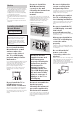
Specifications WM4 a d b c WM1 h i j k e f EN m g l Dimensions: (Approx.) (mm (inch)) a b c d e f g : 860 (33 7/8) : 272 (10 3/4) : 245 (9 3/4) : 11 (7/16) : 354 (14) : 116 (4 5/8) : 77 (3 1/8) h : 563 (22 1/4) i : 533 (21) j : 370 (14 5/8) k : 368 (14 1/2) l : 350 (13 7/8) m : 11 (7/16) Mass (base only): (Approx.) (kg (lb.)) WM4 4.2 (9.3) WM1 3.0 (6.6) Design and specifications are subject to change without notice.
References Measurement for Lateral Shift Bracket installation on the wall Figures in the table may differ slightly depending on the installation.
(mm/inch) 1 Model Name *1 2 *1 (º) K-75S3x / 75S3xC 1 675 / 66 962 / 37 7/8 447 / 17 5/8 34 / 1 3/8 – 95 / 3 3/4 299 / 11 7/8 15 K-65XR7x / 65XR7xC 1 445 / 57 832 / 32 7/8 461 / 18 1/4 – 39 / 1 9/16 82 / 3 1/4 285 / 11 1/4 18 K-65S3x / 65S3xC 1 452 / 57 1/4 836 / 33 449 / 17 3/4 – 31 / 1 1/4 93 / 3 3/4 297 / 11 3/4 18 K-55XR7x / 55XR7xC 1 225 / 48 1/4 709 / 28 461 / 18 1/4 – 101 / 4 82 / 3 1/4 290 / 11 1/2 19 K-55S3x / 55S3xC 1 233 / 48 5/8 713 / 28 1/8 449 / 17 3
Measurement for Wall-Mount Bracket installation on the wall Figures in the table may differ slightly depending on the installation.
(mm/inch) 1 Model Name *1 2 *1 (º) K-75S3x / 75S3xC 1 675 / 66 962 / 37 7/8 363 / 14 3/8 118 / 4 3/4 – 85 / 3 3/8 289 / 11 1/2 15 K-65XR7x / 65XR7xC 1 445 / 57 832 / 32 7/8 377 / 14 7/8 45 / 1 13/16 – 72 / 2 7/8 275 / 10 7/8 18 K-65S3x / 65S3xC 1 452 / 57 1/4 836 / 33 365 / 14 3/8 54 / 2 1/8 – 83 / 3 3/8 287 / 11 3/8 18 K-55XR7x / 55XR7xC 1 225 / 48 1/4 709 / 28 377 / 14 7/8 – 17 / 11/16 72 / 2 7/8 280 / 11 1/8 19 K-55S3x / 55S3xC 1 233 / 48 5/8 713 / 28 1/8 365 /
Informations d’installation pour l’utilisation du Support de fixation murale Sony (SU-WL855) Modèles pris en charge*1 : *1 Pour les noms de modèles réels, les « x »/« xx » indiquent les nombres et/ou les caractères spécifiques à chaque modèle.
Support de fixation murale Sécurité Nous vous remercions d’avoir fait l’acquisition de ce produit. À l’attention des clients Installation du téléviseur ou écran LCD au mur AVERTISSEMENT INSTALLATION PROFESSIONNELLE REQUISE Ce produit doit uniquement être installé par un installateur professionnel formé pour vérifier la résistance du mur qui devra soutenir le poids du téléviseur ou écran LCD.
N’appliquez aucune force excessive sur le produit au cours de l’entretien ou du nettoyage de l’appareil. N’exercez aucune pression excessive sur le dessus du téléviseur ou écran LCD. Dans ce cas, le téléviseur ou écran LCD pourrait tomber et provoquer des blessures ou des dommages matériels. Ne pas placer ce produit près d’appareils médicaux.
Veillez à serrer fermement les vis dans la position prévue. Si vous oubliez, le téléviseur ou écran LCD pourrait tomber et causer des blessures corporelles ou être endommagé. Faites attention à ne pas exposer le téléviseur ou écran LCD à des chocs pendant l’installation. Si le téléviseur ou écran LCD subit des chocs, il pourrait tomber ou se briser. Ceci pourrait causer des blessures. Veillez à installer le téléviseur ou écran LCD sur un mur plat et perpendiculaire.
Avant de commencer ˎ Les illustrations de téléviseur ou de l’écran LCD présentées dans ce manuel sont des exemples utilisés pour fournir des explications claires sur les opérations. Pour cette raison, les illustrations peuvent présenter des différences avec votre téléviseur ou écran LCD réel. Quel est le type de matériau du mur? Commencez par vérifier le type de matériau du mur sur lequel vous souhaitez installer le téléviseur ou écran LCD. Le Support de fixation murale varie selon le type de mur.
Vérification des pièces Fournies avec SU-WL855 ˎ Vérifiez si toutes les pièces sont fournies. WM1 (×1) WM2 (×1) WM4 (×1) M6 (×4) WS1 (×4) WS2 (×6) 6 mm × 20 mm (1/4 pouces × 13/16 pouces) 8 mm × 12 mm (11/32 pouces × 1/2 pouces) WW1 (×6) WW2 (×4) WT1 (×6) WM3 (×4) Fourni avec le téléviseur ou écran LCD Accessoire de fixation murale VS (×4)*1 *1 Uniquement pour certaines régions/pays/modèles.
Préparation pour l’installation ˎ Gardez le Manuel de référence du téléviseur ou écran LCD et le Manuel de configuration à portée de main avant l’installation. ˎ Confirmez la position d’installation de votre téléviseur ou écran LCD. ˎ Préparez les outils suivants : *1 5,5 mm (7/32 pouces) 10 mm (13/32 pouces) *2 *3 1.5 N·m/1,5 N·m {15 kgf·cm} 13 mm (1/2 pouces) 12.
Fixation du Support de fixation murale sur la cloison sèche avec montants 2 3 WM4 Alignez WM4 sur le mur et tracez quatre repères alignés avec les montants. ×4 WM4 WM1 Installation du support de déplacement latéral sur le mur 1 Remarque ˎ Utilisez un niveau pour vérifier que WM4 est de niveau. 4 Décidez de l’emplacement d’installation.
5 Installez ×2 WM4 8 au mur. WS2 WW1 WM1 WM4 WS1 9 Remarque ˎ Utilisez un niveau pour vérifier que WM4 est de niveau. WW2 Tirez le bras du support entièrement vers l’extérieur. Précautions ˎ Ne serrez pas excessivement les tirefonds WS2 . Un serrage incorrect pourrait réduire la capacité de maintien des tirefonds WS2 . 6 Percez les avant-trous inférieurs sur les repères. (Reportez-vous à l’étape 4 pour les instructions de perçage.
2 5 Retirez les vis à l’arrière du téléviseur ou écran LCD. Fixez WM2 au téléviseur ou écran LCD en utilisant M6 . WM2 3 Installez l’accessoire de fixation murale VS (fourni avec le téléviseur ou écran LCD) à l’arrière du téléviseur ou écran LCD (de manière à ce qu’il soit parallèle au mur). VS M6 6 Retirez le support de table du téléviseur ou écran LCD. L’illustration suivante montre un exemple d’opération. • Retirez un seul côté du support de table à la fois.
Remarque ˎ Trois personnes ou plus sont nécessaires pour démonter le support de table. ˎ Veillez à ne pas utiliser une force excessive pour démonter le support de table du téléviseur ou écran LCD, car le téléviseur ou écran LCD pourrait tomber et provoquer des blessures ou endommager le téléviseur ou écran LCD. ˎ Lors de la manipulation du support de table, prenez soin d’éviter d’endommager le téléviseur ou écran LCD.
3 Vissez les côtés gauche et droit du Support de fixation murale. 5 M6 Lorsque vous déplacez le téléviseur ou écran LCD, tenez-le fermement par le bas. Remarque ˎ Il se peut que le téléviseur ou l’écran LCD ne puisse pas se rapprocher du mur selon le type et le nombre de câbles raccordés. Il ne s’agit pas d’une anomalie.
Confirmation de l’achèvement de l’installation Vérifiez les points suivants. ˎ Le cordon et le câble ne sont pas entortillés ou coincés. Fixation du Support de fixation murale au béton solide ou bloc de béton AVERTISSEMENT ˎ Un positionnement incorrect du cordon d’alimentation CA, etc. pourrait provoquer un incendie ou une électrocution par court-circuit. Pour des raisons de sécurité, assurez-vous de confirmer l’achèvement de l’installation.
2 Alignez WM1 sur le mur et tracez quatre repères. 5 Installez WM1 au mur. WM1 ×4 WM1 WS2 WW1 Remarque ˎ Utilisez un niveau pour vérifier que WM1 est de niveau. 3 Remarque ˎ Utilisez un niveau pour vérifier que WM1 est de niveau. Percez des avant-trous sur les repères. Précautions Assurez-vous que l’emplacement sur le mur duquel les trous vont être percés est suffisamment solide pour supporter un poids égal au moins à six fois celui du téléviseur ou de l’écran LCD.
Remarque Préparation pour l’installation du téléviseur ou écran LCD ˎ Assurez-vous de bien serrer l’accessoire de fixation murale VS lors de son installation sur le téléviseur ou l’écran LCD. Utilisez uniquement un tournevis plat pour installer l’accessoire de fixation murale VS . L’utilisation d’un autre outil pourrait entraîner un serrage excessif de l’accessoire de fixation murale VS et endommager le téléviseur ou l’écran LCD.
6 Retirez le support de table du téléviseur ou écran LCD. L’illustration suivante montre un exemple d’opération. • Retirez un seul côté du support de table à la fois. Maintenez fermement le support de table avec les deux mains pendant que l’autre personne soulève le téléviseur ou écran LCD. Installation du téléviseur ou écran LCD sur le mur 1 FR • Répétez les étapes précédentes et retirez l’autre côté du support de table.
3 Vissez les côtés gauche et droit du Support de fixation murale. 5 M6 Lorsque vous déplacez le téléviseur ou écran LCD, tenez-le fermement par le bas. Remarque ˎ Il se peut que le téléviseur ou l’écran LCD ne puisse pas se rapprocher du mur selon le type et le nombre de câbles raccordés. Il ne s’agit pas d’une anomalie.
Confirmation de l’achèvement de l’installation Vérifiez les points suivants. ˎ Le cordon et le câble ne sont pas entortillés ou coincés. AVERTISSEMENT ˎ Un positionnement incorrect du cordon d’alimentation CA, etc. pourrait provoquer un incendie ou une électrocution par court-circuit. Pour des raisons de sécurité, assurez-vous de confirmer l’achèvement de l’installation. Autres informations Pour démonter le téléviseur ou écran LCD, inversez la procédure d’installation précédente.
Spécifications WM4 a d b c WM1 h i j k e f m g l Dimensions : (Environ) (mm (pouces)) a b c d e f g : 860 (33 7/8) : 272 (10 3/4) : 245 (9 3/4) : 11 (7/16) : 354 (14) : 116 (4 5/8) : 77 (3 1/8) h : 563 (22 1/4) i : 533 (21) j : 370 (14 5/8) k : 368 (14 1/2) l : 350 (13 7/8) m : 11 (7/16) Poids (base seulement) : (Environ) (kg (lb.)) WM4 4,2 (9,3) WM1 3,0 (6,6) La conception et les spécifications sont susceptibles d’être modifiées sans préavis.
Références Mesure pour l’installation du support de déplacement latéral sur le mur Les chiffres repris dans le tableau peuvent varier légèrement selon l’installation.
(mm/pouces) 1 Nom du modèle *1 2 *1 (º) K-75S3x / 75S3xC 1 675 / 66 962 / 37 7/8 447 / 17 5/8 34 / 1 3/8 – 95 / 3 3/4 299 / 11 7/8 15 K-65XR7x / 65XR7xC 1 445 / 57 832 / 32 7/8 461 / 18 1/4 – 39 / 1 9/16 82 / 3 1/4 285 / 11 1/4 18 K-65S3x / 65S3xC 1 452 / 57 1/4 836 / 33 449 / 17 3/4 – 31 / 1 1/4 93 / 3 3/4 297 / 11 3/4 18 K-55XR7x / 55XR7xC 1 225 / 48 1/4 709 / 28 461 / 18 1/4 – 101 / 4 82 / 3 1/4 290 / 11 1/2 19 K-55S3x / 55S3xC 1 233 / 48 5/8 713 / 28 1/8 449 /
Mesure pour l’installation du Support de fixation murale Les chiffres repris dans le tableau peuvent varier légèrement selon l’installation.
(mm/pouces) 1 Nom du modèle *1 2 *1 (º) K-75S3x / 75S3xC 1 675 / 66 962 / 37 7/8 363 / 14 3/8 118 / 4 3/4 – 85 / 3 3/8 289 / 11 1/2 15 K-65XR7x / 65XR7xC 1 445 / 57 832 / 32 7/8 377 / 14 7/8 45 / 1 13/16 – 72 / 2 7/8 275 / 10 7/8 18 K-65S3x / 65S3xC 1 452 / 57 1/4 836 / 33 365 / 14 3/8 54 / 2 1/8 – 83 / 3 3/8 287 / 11 3/8 18 K-55XR7x / 55XR7xC 1 225 / 48 1/4 709 / 28 377 / 14 7/8 – 17 / 11/16 72 / 2 7/8 280 / 11 1/8 19 K-55S3x / 55S3xC 1 233 / 48 5/8 713 / 28 1/8
Información de instalación del soporte de montaje mural Sony (SU-WL855) Modelos compatibles*1: *1 En los nombres reales de los modelos, “x”/“xx” indica los números y/o caracteres específicos para cada modelo.
Soporte de montaje mural Seguridad Muchas gracias por la adquisición de este producto. Información para clientes Instalar el TV o pantalla LCD en la pared ADVERTENCIA REQUIERE INSTALACIÓN PROFESIONAL Este producto solo lo debe instalar un instalador profesional que esté capacitado para determinar la resistencia de la pared para soportar el peso del TV o pantalla LCD. Si no se fija correctamente durante la instalación, el TV o pantalla LCD podría caerse y causar lesiones graves.
No manipule el producto con fuerza excesiva cuando realice su limpieza o mantenimiento. No aplique fuerza excesiva en la parte superior del TV o pantalla LCD. Si lo hace, el TV o pantalla LCD puede caerse y provocar daños personales o materiales. No coloque este producto cerca de productos sanitarios. Este producto (incluidos sus accesorios) contiene imanes que pueden interferir con marcapasos, válvulas de derivación programables para tratamientos para la hidrocefalia u otros productos sanitarios.
Asegúrese de apretar los tornillos firmemente en la posición específica. De lo contrario, el TV o pantalla LCD podría caerse y dañarse o provocar daños personales. Tenga cuidado de no someter el TV o pantalla LCD a descargas eléctricas durante la instalación. Si el TV o pantalla LCD recibe algún golpe, puede caerse o romperse. Tales percances podrían causar heridas personales. Asegúrese de instalar el TV o pantalla LCD en una pared que sea perpendicular y plana.
Antes de comenzar ˎ Las ilustraciones del TV o la pantalla LCD que se muestran en este manual son ejemplos usados para proporcionar explicaciones claras de los funcionamientos. Por este motivo, las ilustraciones pueden ser diferentes al TV o pantalla LCD real. ¿De qué está hecha la pared? Primero compruebe el tipo de pared para instalar el TV o pantalla LCD. El soporte de montaje mural varía en función del tipo de la pared.
Inspección de las piezas Piezas suministradas con el soporte SU-WL855 ˎ Verifique que no falten piezas. WM1 (×1) WM2 (×1) WM4 (×1) M6 (×4) WS1 (×4) WS2 (×6) 6 mm × 20 mm (1/4 pulgadas × 13/16 pulgadas) 8 mm × 12 mm (11/32 pulgadas × 1/2 pulgadas) WW1 (×6) WW2 (×4) WT1 (×6) WM3 (×4) Provisto con del TV o pantalla LCD Sujeción del soporte de montaje mural VS (×4)*1 *1 Solo para regiones/países/modelos limitados.
Pasos previos a la instalación ˎ Tenga a mano la Guía de referencia y la Guía de configuración del TV o pantalla LCD antes de comenzar la instalación. ˎ Confirme la posición en la que instalará del TV o pantalla LCD. ˎ Prepare las siguientes herramientas: *1 5,5 mm (7/32 pulgadas) 10 mm (13/32 pulgadas) *2 *3 1.5 N·m/1,5 N·m {15 kgf·cm} 13 mm (1/2 pulgadas) 12.
Sujeción del soporte de montaje mural en la pared de mampostería con pernos de tope 1 2 WM4 Alinee WM4 a la pared y haga cuatro marcas en línea con los pernos. ×4 WM4 WM1 Instalar el soporte de movimiento lateral en la pared 1 Nota ˎ Use un nivel para verificar si WM4 está nivelado. 3 Decida dónde va a realizar la instalación. Asegúrese de que la pared tenga espacio suficiente para el TV o pantalla LCD y pueda soportar un peso que represente al menos seis veces el del TV o pantalla LCD.
4 Instale WM4 ×2 7 en la pared. WS2 WW1 WM1 WM4 WS1 8 Nota ˎ Use un nivel para verificar si WM4 está nivelado. WW2 Jale el brazo del soporte hasta desplegarlo por completo. Precauciones ˎ No ajuste demasiado los pernos de fijación WS2 . El ajuste inadecuado puede reducir la capacidad de retención del perno de fijación WS2 . 5 Perfore orificios guía en las marcas inferiores (consulte las instrucciones de perforación en el paso 4).
2 5 Retire los tornillos de la parte trasera del TV o pantalla LCD. Una la pieza WM2 al TV o pantalla LCD con los tornillos M6 . WM2 3 Coloque la sujeción del soporte de montaje mural VS (provisto con el TV o pantalla LCD) a la parte posterior del TV o pantalla LCD (para que esté paralelo a la pared). M6 6 Separe la mesa auxiliar del TV o pantalla LCD. La siguiente ilustración es un ejemplo de la operación. • Retire un lado del soporte de sobremesa a la vez.
Nota ˎ Se requieren tres o más personas para desmontar el soporte de sobremesa. ˎ Tenga cuidado de no aplicar demasiada fuerza al desmontar el soporte de sobremesa del TV o pantalla LCD ya que puede causar que el TV o pantalla LCD se caiga y cause lesiones personales o daños físicos al TV o pantalla LCD. ˎ Tenga cuidado al manipular el soporte de sobremesa para evitar daños en el TV o pantalla LCD.
3 Atornille el lado izquierdo y el derecho del soporte de montaje mural. 5 Cuando mueva el TV o pantalla LCD, sosténgalo con firmeza desde la parte inferior. Nota M6 ˎ El TV o pantalla LCD puede no moverse cerca de la pared según el tipo y la cantidad de cables utilizados. Esto no es una falla. 6 M6 4 ADVERTENCIA ˎ Para trasladar un TV o pantalla LCD de gran tamaño se necesitan dos o más personas (tres o más personas si se trata de un TV o pantalla LCD de 189,3 cm (75 pulgadas) o más).
Confirmación de la instalación Para confirmar que la instalación se haya realizado correctamente, compruebe lo siguiente. ˎ Ninguno de los cables está retorcido ni apretado por alguna pieza. Coloque el soporte de montaje mural al concreto sólido o al bloque de concreto ADVERTENCIA ˎ No ubicar correctamente el cable de alimentación de CA u otros cables podría provocar un incendio o descargas eléctricas si se produce un cortocircuito.
2 Alinee la pieza WM1 con el muro y haga cuatro marcas. 5 Instale WM1 en la pared. WM1 ×4 WM1 WS2 WW1 Nota ˎ Use un nivel para verificar si WM1 está nivelado. 3 Nota Perfore orificios en las marcas. ˎ Use un nivel para verificar si WM1 está nivelado. Asegúrese de que la ubicación en la pared donde se van a perforar los agujeros sea lo suficientemente fuerte para soportar un peso de al menos seis veces el peso del TV o pantalla LCD. ˎ No ajuste demasiado los pernos de fijación WS2 .
Nota Preparar la instalación del TV o pantalla LCD ˎ Asegúrese de sujetar la sujeción del soporte de montaje mural VS al fijarlo al TV o pantalla LCD. Utilice solamente un destornillador de cabeza plana para instalar la sujeción del soporte de montaje mural VS . El uso de otra herramienta puede causar el exceso de ajuste del par de apriete en la sujeción del soporte de montaje mural VS y dañar el TV o la pantalla LCD.
6 Separe la mesa auxiliar del TV o pantalla LCD. La siguiente ilustración es un ejemplo de la operación. • Retire un lado del soporte de sobremesa a la vez. Sostenga firmemente el soporte de sobremesa con ambas manos y de forma segura mientras otras personas levantan el TV o pantalla LCD. Instalar el TV o pantalla LCD en la pared 1 ES • Repita el paso anterior y retire el otro lado del soporte de sobremesa. Nota ˎ Se requieren tres o más personas para desmontar el soporte de sobremesa.
3 Atornille el lado izquierdo y el derecho del soporte de montaje mural. 5 Cuando mueva el TV o pantalla LCD, sosténgalo con firmeza desde la parte inferior. Nota M6 ˎ El TV o pantalla LCD puede no moverse cerca de la pared según el tipo y la cantidad de cables utilizados. Esto no es una falla. 6 M6 4 ADVERTENCIA ˎ Para trasladar un TV o pantalla LCD de gran tamaño se necesitan dos o más personas (tres o más personas si se trata de un TV o pantalla LCD de 189,3 cm (75 pulgadas) o más).
Confirmación de la instalación Para confirmar que la instalación se haya realizado correctamente, compruebe lo siguiente. ˎ Ninguno de los cables está retorcido ni apretado por alguna pieza. ADVERTENCIA ˎ No ubicar correctamente el cable de alimentación de CA u otros cables podría provocar un incendio o descargas eléctricas si se produce un cortocircuito. No olvide confirmar que la instalación se haya realizado correctamente para garantizar la seguridad.
Especificaciones WM4 a d b c WM1 h i j k e f m g l Dimensiones: (Aprox.) (mm (pulgadas)) a b c d e f g : 860 (33 7/8) : 272 (10 3/4) : 245 (9 3/4) : 11 (7/16) : 354 (14) : 116 (4 5/8) : 77 (3 1/8) h : 563 (22 1/4) i : 533 (21) j : 370 (14 5/8) k : 368 (14 1/2) l : 350 (13 7/8) m : 11 (7/16) Peso (solo de la base): (Aprox.) (kg (lb.)) WM4 4,2 (9,3) WM1 3,0 (6,6) El diseño y las especificaciones pueden cambiar sin aviso.
Referencias Mediciones para la instalación del soporte de movimiento lateral en la pared Las cifras de la tabla pueden variar levemente según el tipo de instalación.
(mm/pulgadas) 1 Nombre de modelo *1 2 *1 (º) K-75S3x / 75S3xC 1 675 / 66 962 / 37 7/8 447 / 17 5/8 34 / 1 3/8 – 95 / 3 3/4 299 / 11 7/8 15 K-65XR7x / 65XR7xC 1 445 / 57 832 / 32 7/8 461 / 18 1/4 – 39 / 1 9/16 82 / 3 1/4 285 / 11 1/4 18 K-65S3x / 65S3xC 1 452 / 57 1/4 836 / 33 449 / 17 3/4 – 31 / 1 1/4 93 / 3 3/4 297 / 11 3/4 18 K-55XR7x / 55XR7xC 1 225 / 48 1/4 709 / 28 461 / 18 1/4 – 101 / 4 82 / 3 1/4 290 / 11 1/2 19 K-55S3x / 55S3xC 1 233 / 48 5/8 713 / 28 1/8
Mediciones para la instalación del soporte de montaje mural Las cifras de la tabla pueden variar levemente según el tipo de instalación.
(mm/pulgadas) 1 Nombre de modelo *1 2 *1 (º) K-75S3x / 75S3xC 1 675 / 66 962 / 37 7/8 363 / 14 3/8 118 / 4 3/4 – 85 / 3 3/8 289 / 11 1/2 15 K-65XR7x / 65XR7xC 1 445 / 57 832 / 32 7/8 377 / 14 7/8 45 / 1 13/16 – 72 / 2 7/8 275 / 10 7/8 18 K-65S3x / 65S3xC 1 452 / 57 1/4 836 / 33 365 / 14 3/8 54 / 2 1/8 – 83 / 3 3/8 287 / 11 3/8 18 K-55XR7x / 55XR7xC 1 225 / 48 1/4 709 / 28 377 / 14 7/8 – 17 / 11/16 72 / 2 7/8 280 / 11 1/8 19 K-55S3x / 55S3xC 1 233 / 48 5/8 713 / 28