Sound Bar Bracket Support de barre de son Soporte para barra de sonido Installation Information EN Informations d’installation FR Información para la instalación ES 安装信息 CS Lea este manual antes de usar el producto V-821-100-11(1) SU-WB1
Installation Information for Using Sony Sound Bar Bracket (SU-WB1) Supported models: HT-A5000 / A3000 214.8 cm (85 inches) 194.7 cm (77 inches) / 189.3 cm (75 inches) / 163.9 cm (65 inches) / 138.8 cm (55 inches) 400 400 300 300 To Customers For product protection and safety reasons, Sony strongly recommends that installation of your TV or LCD Display with Sound Bar be performed by Sony dealers or licensed contractors. Do not attempt to install it yourself.
Sound Bar Bracket On Safety Thank you for purchasing this product. To Customers Installing the TV or LCD Display with Sound Bar to the Wall WARNING PROFESSIONAL INSTALLATION REQUIRED This product should only be installed by a professional installer who is trained to determine the strength of the wall for withstanding the TV or LCD Display with Sound Bar weight. If it is not properly secured during installation, the TV or LCD Display with Sound Bar may fall and cause serious injury.
Notice Do not use the Sound Bar Bracket in a place where it is subjected to mechanical vibrations. Installing the Sound Bar Bracket To Sony Dealers WARNING The following instructions are for Sony dealers only. Be sure to read safety precautions described above and pay special attention to safety during the installation, maintenance and checking of this product. Be sure to install the Sound Bar Bracket securely to the WallMount Bracket following the instructions in this instruction manual.
Before Getting Started ˎ The TV or LCD Display with Sound Bar illustrations shown in this manual are examples used to provide clear explanations of the operations. For this reason, the illustrations may appear different from your actual TV or LCD Display with Sound Bar. Checking the Parts Supplied with SU-WB1 ˎ Verify that all the parts are included.
Preparing for Installation ˎ Have the Sound Bar Bracket Safety Information and Sound Bar Bracket Installation Guide at hand before installation. ˎ Prepare the following tools: 1.
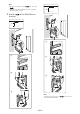
Installing the Sound Bar Bracket to the Wall-Mount Bracket 1 2 Set the length of SB1 . Refer to the table. Set the length of SB2 . Attach the screws M4B according to the table. Attach SB2 to SB1 using M5 .
Note ˎ Be sure to insert the end of SB2 into the slot of SB1 . ˎ Adjust the position required for your Sound Bar before fixing the screws. 3 400 400 Attach SB1 to the Wall-Mount Bracket. 300 300 M4A M4A M4A Note ˎ Be sure to insert the end of SB1 into the slot of the Wall-Mount Bracket.
4 Attach SB4 or SB5 . (Depending on the Sound Bar model). Installing the Sound Bar on the Wall 1 HT-A5000 Connect the cables from the TV or LCD Display to the Sound Bar. SB4 M4A *1 EN HT-A3000 SB5 *1 Only for limited region/country/model.
2 Attach the Sound Bar to the Sound Bar Bracket. 3 Route the cables for the TV or LCD Display and Sound Bar.
4 Attach SB6 and SB3 . 5 Secure the Sound Bar (HT-A5000 only).
Confirming the Completion of the Installation Check the following points. ˎ The cord and the cable are not twisted or pinched. WARNING ˎ Improper placement of the AC power cord, etc. may cause fire or electric shock through a short circuit. Be sure to confirm the completion of the installation for safety. Other Information When removing the Sound Bar, reverse the previous installation procedure. WARNING ˎ Two or more persons are needed to transport a Sound Bar.
Specifications a b c e d f Dimension: (Approx.) (mm (inch)) a : 1 114 (43 7/8) b : 565 (22 1/4) c : 358.5 (14 1/8) d : 309 (12 1/4) e : 13 (17/32) f : 18 (23/32) EN Mass (base only): (Approx.) (kg (lb.)) 2.9 (6.4) Design and specifications are subject to change without notice.
Informations d’installation pour l’utilisation du Support de barre de son Sony (SU-WB1) Modèles pris en charge : HT-A5000 / A3000 214,8 cm (85 pouces) 194,7 cm (77 pouces) / 189,3 cm (75 pouces) / 163,9 cm (65 pouces) / 138,8 cm (55 pouces) 400 400 300 300 À l’attention des clients Pour des raisons de sécurité et de protection du produit, Sony recommande vivement de faire installer votre téléviseur ou écran LCD avec barre de son par des détaillants Sony ou des installateurs agréés.
Support de barre de son Sécurité Nous vous remercions d’avoir fait l’acquisition de ce produit. À l’attention des clients Installation du téléviseur ou écran LCD avec barre de son au mur AVERTISSEMENT INSTALLATION PROFESSIONNELLE REQUISE Ce produit doit uniquement être installé par un installateur professionnel formé pour vérifier la résistance du mur qui devra soutenir le poids du téléviseur ou écran LCD avec barre de son.
Ne pas placer ce produit près d’appareils médicaux. Ce produit (y compris les accessoires) est doté d’un ou plusieurs aimants qui peuvent interférer avec le fonctionnement des stimulateurs cardiaques, robinets de dérivation programmables pour traitement d’hydrocéphalie ou autres appareils médicaux. Ne placez pas ce produit près des personnes qui utilisent de tels appareils médicaux. Consultez votre médecin avant d’utiliser ce produit si vous utilisez de tels appareils médicaux.
Avant de commencer ˎ Les illustrations du téléviseur ou écran LCD avec barre de son présentées dans ce manuel sont des exemples utilisés pour fournir des explications claires sur les opérations. Pour cette raison, les illustrations peuvent présenter des différences avec votre téléviseur ou écran LCD avec barre de son réel. Vérification des pièces Fournies avec SU-WB1 ˎ Vérifiez si toutes les pièces sont fournies.
Préparation pour l’installation ˎ Gardez les Consignes de sécurité du Support de barre de son et le Guide d’installation du Support de barre de son à portée de main avant l’installation. ˎ Préparez les outils suivants : 1,5 N·m {15 kgf.
Installation du Support de barre de son sur le Support de fixation murale 1 2 Définissez la longueur de SB2 . Fixez les vis M4B comme indiqué dans le tableau. Fixez SB2 à SB1 à l’aide de M5 . Définissez la longueur de SB1 . Reportez-vous au tableau.
Remarque ˎ Assurez-vous d’insérer l’extrémité de SB2 dans la fente de SB1 . ˎ Ajustez la position requise pour votre barre de son avant de fixer les vis. 3 400 400 Fixez SB1 au Support de fixation murale. 300 300 M4A M4A M4A Remarque ˎ Assurez-vous d’insérer l’extrémité de SB1 dans la fente du Support de fixation murale.
4 Fixez SB4 ou SB5 . (En fonction du modèle de barre de son). Installation de la barre de son sur le mur 1 HT-A5000 SB4 Raccordez les câbles du téléviseur ou écran LCD à la barre de son. M4A *1 FR HT-A3000 SB5 M4A *1 Uniquement pour certaines régions/pays/ modèles.
2 Fixez la barre de son au Support de barre de son. 3 HT-A5000 Acheminez les câbles pour le téléviseur ou écran LCD et la barre de son.
4 Fixez SB6 et SB3 . 5 Fixez la barre de son (HT-A5000 uniquement).
Confirmation de l’achèvement de l’installation Vérifiez les points suivants. ˎ Le cordon et le câble ne sont pas entortillés ou coincés. AVERTISSEMENT ˎ Un positionnement incorrect du cordon d’alimentation CA, etc. pourrait provoquer un incendie ou une électrocution par court-circuit. Pour des raisons de sécurité, assurez-vous de confirmer l’achèvement de l’installation. Autres informations Pour démonter la barre de son, inversez la procédure d’installation précédente.
Spécifications a b c e d f Dimensions : (Environ) (mm (pouces)) a : 1 114 (43 7/8) b : 565 (22 1/4) c : 358,5 (14 1/8) d : 309 (12 1/4) e : 13 (17/32) f : 18 (23/32) FR Poids (base seulement) : (Environ) (kg (lb.)) 2,9 (6,4) La conception et les spécifications sont susceptibles d’être modifiées sans préavis.
Información de instalación para usar el Soporte para barra de sonido Sony (SU-WB1) Modelos compatibles: HT-A5000 / A3000 214,8 cm (85 pulgadas) 194,7 cm (77 pulgadas) / 189,3 cm (75 pulgadas) / 163,9 cm (65 pulgadas) / 138,8 cm (55 pulgadas) 400 400 300 300 Información para clientes Para proteger el producto y por motivos de seguridad, Sony recomienda enérgicamente dejar la instalación del TV o pantalla LCD con la Barra de sonido en manos de un distribuidor de Sony o un contratista certificado.
Soporte para barra de sonido Seguridad Muchas gracias por la adquisición de este producto. Información para clientes Instalar el TV o pantalla LCD con la barra de sonido en la pared ADVERTENCIA REQUIERE INSTALACIÓN PROFESIONAL Este producto solo lo debe instalar un instalador profesional que esté capacitado para determinar la resistencia de la pared para soportar el peso del TV o pantalla LCD con la barra de sonido.
No coloque este producto cerca de productos sanitarios. Este producto (incluidos sus accesorios) contiene imanes que pueden interferir con marcapasos, válvulas de derivación programables para tratamientos para la hidrocefalia u otros productos sanitarios. No coloque el dispositivo cerca de personas que usen tales dispositivos médicos. Consulte con su médico antes de usar este producto si usa un dispositivo médico tal.
Antes de comenzar ˎ Las ilustraciones del TV o la pantalla LCD con la Barra de sonido que se muestran en este manual son ejemplos usados para proporcionar explicaciones claras de los funcionamientos. Por este motivo, las ilustraciones pueden ser diferentes al TV o pantalla LCD con la Barra de sonido real. Inspección de las piezas Piezas suministradas con el soporte SU-WB1 ˎ Verifique que no falten piezas.
Pasos previos a la instalación ˎ Antes de la instalación, tenga a mano la Información sobre seguridad del Soporte para barra de sonido y la Guía de instalación del Soporte para barra de sonido. ˎ Prepare las siguientes herramientas: 1,5 N· m {15 kgf.
Instalar el Soporte para barra de sonido en el Soporte de montaje mural 1 Fije la longitud de Consulte la tabla. SB1 2 Fije la longitud de SB2 . Fije los tornillos M4B de acuerdo con la tabla. Fije SB2 a SB1 usando M5 . .
Nota ˎ Asegúrese de insertar el extremo de SB2 a la ranura de SB1 . ˎ Ajuste la posición requerida para su Barra de sonido antes de fijar los tornillos. 3 400 400 Fije SB1 al Soporte de montaje mural. 300 300 M4A M4A M4A Nota ˎ Asegúrese de insertar el extremo de SB1 en la ranura del Soporte de montaje mural.
4 Fije SB4 o SB5 . (Según el modelo de la Barra de sonido). Instalar la Barra de sonido en la pared 1 HT-A5000 SB4 Conecte los cables desde el TV o pantalla LCD a la barra de sonido. M4A *1 ES HT-A3000 SB5 M4A *1 Solo para regiones/países/modelos limitados.
2 Fije la barra de sonido al Soporte para barra de sonido. 3 HT-A5000 Tienda los cables para el TV o la pantalla LCD y la barra de sonido.
4 Fije SB6 y SB3 5 . Asegure la Barra de sonido (Solo HT-A5000).
Confirmación de la instalación Para confirmar que la instalación se haya realizado correctamente, compruebe lo siguiente. ˎ Ninguno de los cables está retorcido ni apretado por alguna pieza. ADVERTENCIA ˎ No ubicar correctamente el cable de alimentación de CA u otros cables podría provocar un incendio o descargas eléctricas si se produce un cortocircuito. No olvide confirmar que la instalación se haya realizado correctamente para garantizar la seguridad.
Especificaciones a b c e d f Dimensiones: (Aprox.) (mm (pulgadas)) a : 1 114 (43 7/8) b : 565 (22 1/4) c : 358,5 (14 1/8) d : 309 (12 1/4) e : 13 (17/32) f : 18 (23/32) Peso (solo de la base): (Aprox.) (kg (lb.)) 2,9 (6,4) El diseño y las especificaciones pueden cambiar sin aviso.
Sony 无线家庭音箱支架安装信息(SU-WB1) 支持型号: HT-A5000 / A3000 214.8 cm(85 英寸) 194.7 cm (77 英寸) / 189.3 cm(75 英寸)/ 163.9 cm(65 英寸)/ 138.
无线家庭音箱支架 安全须知 感谢您购买本产品。 致用户 将带无线家庭音箱的电视机或 LCD 显示器 安装到墙上 警告 在操作无线家庭音箱或无线 家庭音箱支架时,请勿旋转 电视机或 LCD 显示器。 致用户 警告 若不遵守下列预先注意事项,则可能会导 致火灾、触电和产品掉落风险,进而造成 严重伤害,甚至死亡。 确保委托授权承包商进行产 品安装并在安装过程中避免 儿童靠近。 Sony 经销商须知 如果无线家庭音箱支架或电视机或 LCD 显示器 安装不正确,则可能会发生以下事故。确保由 授权承包商进行产品安装。 带无线家庭音箱的电视机或 LCD 显示器可能 会掉落并造成严重伤害,如擦伤或骨折。 如果带无线家庭音箱支架的挂壁式支架的所 在墙体不稳定、不平整或与地板不垂直,则 装置可能会坠落并造成人员伤害或财产损 失。墙壁应能够支撑至少四倍于带无线家庭 音箱的电视机或 LCD 显示器的重量。 (请参阅您的电视机或 LCD 显示器和无线家 庭音箱的使用说明书,以了解其重量。) 如果带无线家庭音箱支架的挂壁式支架在墙 上安装得不够牢固,则装置可能会掉落并造 成人员伤害或财产损失。 安装本产品需
务必按照本使用说明书中的 指示,将无线家庭音箱支架 牢固地安装到挂壁式支架 上。 请确保电视机或 LCD 显示 器与无线家庭音箱之间保留 一定距离,如下图所示: 如果任何螺钉松动或脱落,则无线家庭音箱支 架可能会掉落并造成人身伤害或财产损失。 > 70 mm 请务必在指定的位置拧紧螺 丝。 安装无线家庭音箱支架时, 请确保不要损坏电视机或 LCD 显示器的边角。安装时 请务必 小心,防止头部或身体撞到 电视机或 LCD 显示器的边 角。 否则,无线家庭音箱可能会掉落并导致人身伤 害或无线家庭音箱损坏。 在安装过程中,注意切勿使 无线家庭音箱受到震动。 无线家庭音箱受到震动可能会掉落或破裂。进 而可能会造成伤害。 妥善安装无线家庭音箱后, 正确固定电缆。 如果人员或物体与电缆纠缠在一起,则可能会 导致人身伤害或无线家庭音箱损坏。 请勿让交流电源线或连接电 缆受到挤压。 若交流电源线或连接电缆被挤压于电视机或 LCD 显示器和墙壁之间,或被外力弯曲或扭 曲,内部导线则可能裸露并导致短路或停电。 进而可能会导致火灾或触电。 请务必遵循本使用说明书 中的说明正确使用所提供 的螺丝和配件。如果您使 用
事先准备 ˎ 本手册中所示的带无线家庭音箱的电视或 LCD 显示器的图例,是为了清晰地对操作进行说明的示 例。因此,图例可能看起来与您实际带有无线家庭音箱的电视或 LCD 显示器不同。 检查部件 SU-WB1 随附部件 ˎ 请检查所有部件是否均已包含在内。 SB1 (×1) SB2 (×2) SB3 (×1) SB4 (×2) SB5 (×2) SB6 (×4) CS M4A (×18) M4B (×2) M5 (×8) WT2 (×15) WC1 (×10) WC2 (×1) − 5 (CS) −
安装准备 ˎ 安装前,准备好无线家庭音箱支架安全信息、无线家庭音箱支架安装指南。 ˎ 准备以下工具: 1.
將无线家庭音箱支架安装至挂壁 式支架 1 2 设定 SB2 的长度。 根据表格连接螺丝 M4B 。 使用 M5 將 SB2 连接至 SB1 。 设定 SB1 的长度。 请参阅表格。 M4B SB2 C H 11 SB2 10 M4B 11 B H A B A 35 ~ 50 55 ~ 60 55 ~ 65 ~35 65~ (1 7/16 (2 1/4 ~ (2 1/4 ~ (~1 7/16) (2 5/8~) ~ 2) 2 3/8) 2 5/8) 8 7 6 95 ~ 105 (3 3/4 ~ 4 1/4) 8 8 7 6 5 105 ~ 115 (4 1/4 ~ 4 5/8) 8 7 6 5 4 115 ~ 125 (4 5/8 ~ 5) 7 6 5 4 3 125 ~ 135 (5 ~ 5 3/8) 6 5 4 3 2 135 ~ 145 (5 3/8 ~ 5 3/4) 5 4 3 2 1 145 ~ 155 (5 3/4 ~ 6 1/8) 4 3 2 1 0 HT-A3000
3 將 SB1 连接至 Sony 挂壁式支 架。 400 400 300 300 M4A M4A M4A M4A 注意 ˎ 请务必將 − 8 (CS) − SB1 末端插入到挂壁式支架槽中。
4 连接 SB4 或 SB5 。 (视无线家庭音箱型号而定)。 在墙壁上安装无线家庭音箱 1 HT-A5000 请用电缆连接电视或 LCD 显示器 与无线家庭音箱。 SB4 光纤输出 输入 M4A *1 S- 中置 扬声器输入 HT-A3000 CS SB5 *1 仅针对有限的地区/国家/型号。 M4A − 9 (CS) −
2 將无线家庭音箱固定在无线家庭音 箱支架上。 3 为电视或 LCD 显示器与无线家庭 音箱布线。 HT-A5000 HT-A3000 WC1 WC2 − 10 (CS) − WT2
4 连接 SB6 和 SB3 。 5 固定无线家庭音箱(仅 HT-A5000)。 HT-A5000 SB6 SB3 SB4 M4A 6 − 11 (CS) − CS
确认安装完成 请检查以下几点。 ˎ 电线和电缆无扭曲或挤压。 警告 ˎ 交流电源线布置不当等可能会因短路而引起火灾或触电。 为了安全起见,请务必确认安装完成。 其他信息 拆卸本无线家庭音箱时,请反向执行上述安装程 序。 警告 ˎ 确保由两人或两人以上搬运无线家庭音箱。 − 12 (CS) −
规格 a b c e d f 尺寸:(约)(mm) a : 1 114 b : 565 c : 358.5 d : 309 e : 13 f : 18 CS 重量(仅基座):(约)(kg) 2.