
user manual


Table Of Contents
- Chapter 1 Overview
- Chapter 2 Locations and Functions of Parts and Controls
- Chapter 3 Setting Up the VTR
- Chapter 4 Menu Settings
- 4-1 Registering and Storing Menu Settings
- 4-2 HOME Menu
- 4-2-1 Selecting the Output Signals(PB/EE)
- 4-2-2 Record Inhibit Mode (REC INH)
- 4-2-3 Selecting the Edit Mode and Edit Channel (ASSEMBLE or INS CUE)
- 4-2-4 Preread Settings (PRE READ)
- 4-2-5 Still-Picture Output (FREEZE)
- 4-2-6 Selecting the Capstan Servo Lock Mode (CAP LOCK)
- 4-2-7 Setting the Preroll Time (PREROLL TIME)
- 4-2-8 Selecting DMC Playback (DMC)
- 4-2-9 Recalling Edit Points (LAST EDIT)
- 4-3 TC Menu
- 4-3-1 Setting the Time Data (TIMER SEL/RESET/SET/HOLD)
- 4-3-2 Setting the Time Code Reader (TCR SEL)
- 4-3-3 Setting the Time Code Generator (TCG SOURCE/MODE)
- 4-3-4 Selecting the Time Code Running Mode (RUN MODE)
- 4-3-5 Selecting the Drop Frame Mode (DF/NDF)
- 4-3-6 Inserting VITC input source (VITC)
- 4-3-7 Selecting CTL Display Mode (TAPE TIMER)
- 4-3-8 Presetting Pull Down Time Code (PDPSET MENU)(when HKDV-507/507D is installed)
- 4-3-9 Presetting for Conversion From 24-frame Into 25-frame Time Code
- 4-3-10 Conversion of Time Code During Playback in 25F Mode (TC CONV)
- 4-3-11 Displaying the Pull Down Time Code (when HKDV-507/507D is installed)
- 4-3-12 Superimposition of Character Information (PD CHARA/CHARA SUPER/H-POS/V-POS)
- 4-3-13 Setting the VITC Insertion Line (VITC POS-1/POS-2)
- 4-3-14 Presetting for Conversion From 25-frame Into 24-frame Time Code
- 4-3-15 Conversion of Time Code During Playback in 24F Mode (TC CONV)
- 4-4 CUE Menu
- 4-5 PF1 Menu (Factory Settings)
- 4-6 PF2 Menu (Factory Settings)
- 4-7 SET UP Menu
- Chapter 5 Recording/Playback
- 5-1 Preparing for Recording
- 5-2 Recording
- 5-3 Preparing for Playback
- 5-3-1 Setting Switches and Menus
- 5-3-2 Adjusting the Audio Playback Level
- 5-3-3 Selecting the HD-SD Conversion Mode (when HKDV-501A is installed)
- 5-3-4 Selecting the Conversion Mode of the Effective Scanning Line Number
- 5-3-5 Improving the Vertical Resolution during Slow-Motion Playback (when HKDV-502 is installed)
- 5-4 Playback
- Chapter 6 Editing
- Appendix
- Maintenance
- Specifications
- Operation Information Display
- Error Messages and Warning Messages
- Glossary
- Menu List
- Items Related to the Hours Meter (H01~)
- Items Related to VTR Operations (001~)
- Items Related to Operation Panels (101~)
- Items Related to Remote Interface (201~)
- Items Related to Editing (301~)
- Items Related to Prerolling (401~)
- Items Related to Recording Protection (501~)
- Items Related to the Time Code (601~)
- Items Related to the Video Control (701~)
- Items Related to the Audio Control (801~)
- Items Related to Digital Processing (901~)
- Items Related to the Pull Down Control (A01~)
- Other Items (T01~)
- Index
- Table of Functions (Factory Default Settings)
4-2 HOME Menu
4-16 Chapter 4 Menu Settings
Chapter 4 Menu Settings
VTR SETUP MENU 017. PB/
EE SELECT MENU settings
Output signals while the
[F1] (PB/EE) button is held
down
PB/MU EE/EE
PB/PB
EE/EE
EE/EE
PB/MU
4-2-1 Selecting the Output
Signals(PB/EE)
The audio/video output signals from the line output
and monitor output connectors can be temporarily
changed from their current settings to another set of
settings by pressing the [F1] (PB/EE) button. The
video, digital audio, and analog cue channel output
signals are toggled to the other set of settings while the
button is pressed.
Output Signal Selection
Output signal selection is made using the 017.PB/EE
SELECT MENU. Output signal types for different
operation modes of this VTR are shown below.
1) Output signals during playback are PB/PB only. Output
signals cannot be selected with 017.PB/EE SELECT
MENU.
2) When the INPUT CHECK button is held down, the
INPUT signals (audio and video) are output. Output
signals cannot be selected with 017.PB/EE SELECT
MENU. When the INPUT signals are output, only
monitor output is changed. Line output signals are not
changed.
3) Pressing the [F1] (PB/EE) button changes the output
signals during shuttle mode in the following ways.
Note
When PB/PB is selected during shuttle mode, audio
output is muted for playback speeds of more than –1 or
+2 times normal speed.
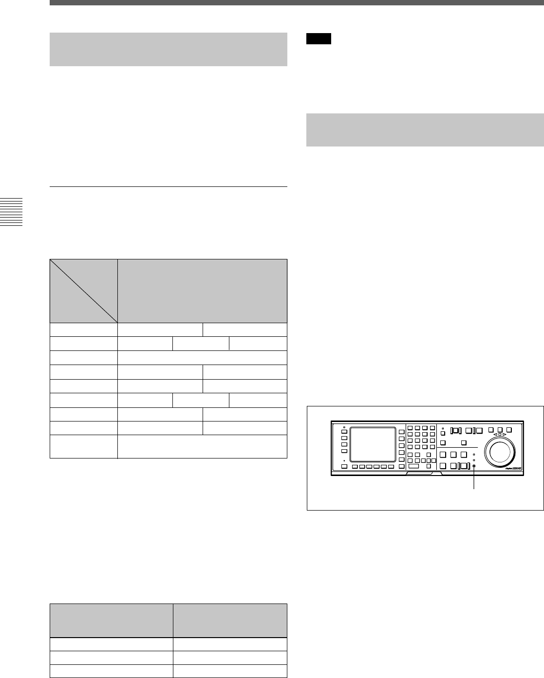
4-2-2 Record Inhibit Mode
(REC INH)
Record inhibit mode is selected by pressing the [F2]
(REC INH) button. Every time the button is pressed,
the setting toggles between off and <all, crash REC,
video/CTL, audio/CTL>.
The record inhibit area is selected using the 003.REC
INHIBIT AREA select setting in the VTR SETUP
menu.
all: All recording is prohibited. (The REC INHIBIT
indicator will be lit.)
crash REC: The normal record mode is disabled.
Use this setting when you want to record only
during assemble editing or insert editing.
video/CTL: Video and CTL signal recording is
inhibited.
Audio/CTL: Audio and CTL signal recording is
inhibited.
[casst]: This is displayed when recording is inhibited
because the record-protect plug is set. This setting
cannot be selected.
VTR
Operation
Mode
Standby off
Output
Channel
Video/Audio
EE/EE
PB/MU
Standby on PB/MU EE/EE
Playback PB/PB
1)
Record EE/EE PB/PB
Shuttle
3)
PB/MU EE/EE PB/PB
Jog PB/PB PB/MU
Variable PB/PB PB/MU
INPUT CHECK
button
INPUT
2)
REC INHIBIT indicator
Edit EE/EE PB/PB
EE/MU