
user manual


Table Of Contents
- Chapter 1 Overview
- Chapter 2 Locations and Functions of Parts and Controls
- Chapter 3 Setting Up the VTR
- Chapter 4 Menu Settings
- 4-1 Registering and Storing Menu Settings
- 4-2 HOME Menu
- 4-2-1 Selecting the Output Signals(PB/EE)
- 4-2-2 Record Inhibit Mode (REC INH)
- 4-2-3 Selecting the Edit Mode and Edit Channel (ASSEMBLE or INS CUE)
- 4-2-4 Preread Settings (PRE READ)
- 4-2-5 Still-Picture Output (FREEZE)
- 4-2-6 Selecting the Capstan Servo Lock Mode (CAP LOCK)
- 4-2-7 Setting the Preroll Time (PREROLL TIME)
- 4-2-8 Selecting DMC Playback (DMC)
- 4-2-9 Recalling Edit Points (LAST EDIT)
- 4-3 TC Menu
- 4-3-1 Setting the Time Data (TIMER SEL/RESET/SET/HOLD)
- 4-3-2 Setting the Time Code Reader (TCR SEL)
- 4-3-3 Setting the Time Code Generator (TCG SOURCE/MODE)
- 4-3-4 Selecting the Time Code Running Mode (RUN MODE)
- 4-3-5 Selecting the Drop Frame Mode (DF/NDF)
- 4-3-6 Inserting VITC input source (VITC)
- 4-3-7 Selecting CTL Display Mode (TAPE TIMER)
- 4-3-8 Presetting Pull Down Time Code (PDPSET MENU)(when HKDV-507/507D is installed)
- 4-3-9 Presetting for Conversion From 24-frame Into 25-frame Time Code
- 4-3-10 Conversion of Time Code During Playback in 25F Mode (TC CONV)
- 4-3-11 Displaying the Pull Down Time Code (when HKDV-507/507D is installed)
- 4-3-12 Superimposition of Character Information (PD CHARA/CHARA SUPER/H-POS/V-POS)
- 4-3-13 Setting the VITC Insertion Line (VITC POS-1/POS-2)
- 4-3-14 Presetting for Conversion From 25-frame Into 24-frame Time Code
- 4-3-15 Conversion of Time Code During Playback in 24F Mode (TC CONV)
- 4-4 CUE Menu
- 4-5 PF1 Menu (Factory Settings)
- 4-6 PF2 Menu (Factory Settings)
- 4-7 SET UP Menu
- Chapter 5 Recording/Playback
- 5-1 Preparing for Recording
- 5-2 Recording
- 5-3 Preparing for Playback
- 5-3-1 Setting Switches and Menus
- 5-3-2 Adjusting the Audio Playback Level
- 5-3-3 Selecting the HD-SD Conversion Mode (when HKDV-501A is installed)
- 5-3-4 Selecting the Conversion Mode of the Effective Scanning Line Number
- 5-3-5 Improving the Vertical Resolution during Slow-Motion Playback (when HKDV-502 is installed)
- 5-4 Playback
- Chapter 6 Editing
- Appendix
- Maintenance
- Specifications
- Operation Information Display
- Error Messages and Warning Messages
- Glossary
- Menu List
- Items Related to the Hours Meter (H01~)
- Items Related to VTR Operations (001~)
- Items Related to Operation Panels (101~)
- Items Related to Remote Interface (201~)
- Items Related to Editing (301~)
- Items Related to Prerolling (401~)
- Items Related to Recording Protection (501~)
- Items Related to the Time Code (601~)
- Items Related to the Video Control (701~)
- Items Related to the Audio Control (801~)
- Items Related to Digital Processing (901~)
- Items Related to the Pull Down Control (A01~)
- Other Items (T01~)
- Index
- Table of Functions (Factory Default Settings)
Menu List
A-32 Appendix
Appendix
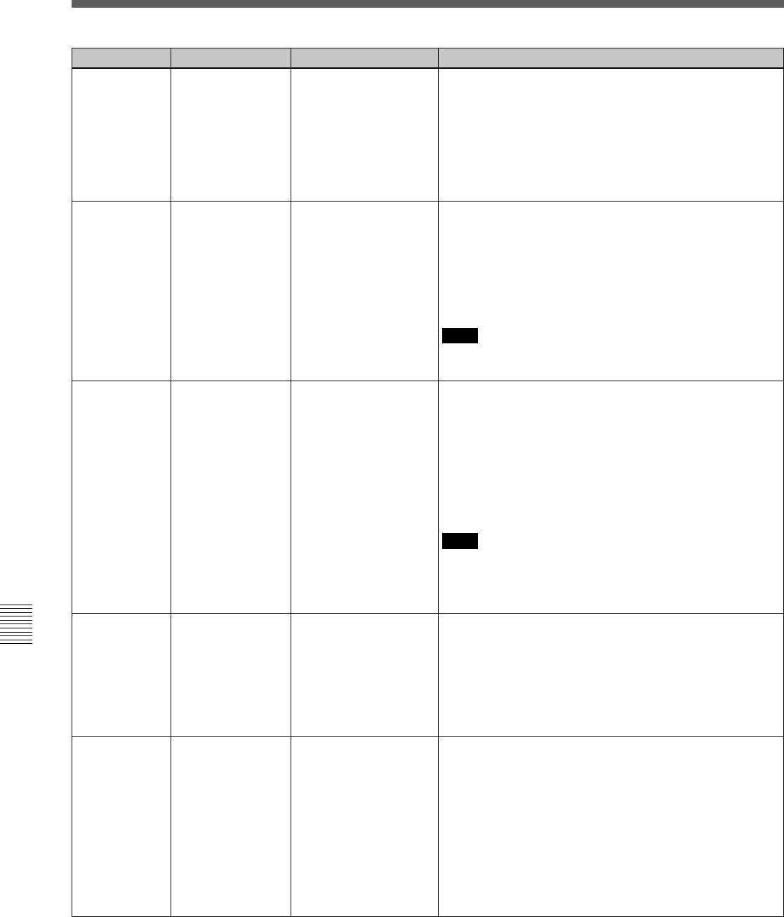
Item number Settable rangeItem
622 CHARACTER H-
POSITION
0
.
.
.
[8]
.
.
.
15
Sets the horizontal position of text information
superimposed on the signal output from the MONITOR
connector of HD SDI OUTPUT, the D CONV. OUT
(OPTION) COMPOSITE (SUPER) connector, the 3
(SUPER) connector of D CONV. SDI OUT (OPTION) and
the PULL DOWN OUT connectors. A setting of 0 displays
the information at the left edge of the screen, and the
position moves to the right as the setting is increased. There
are 16 possible settings, from 0 to 15
623 CHARACTER V-
POSITION
0
.
.
.
[22]
.
.
.
23
Sets the vertical position of text information superimposed
on the signal output from the MONITOR connector of HD
SDI OUTPUT, the D CONV. OUT (OPTION) COMPOSITE
(SUPER) connector, the 3 (SUPER) connector of D CONV.
SDI OUT (OPTION) and the PULL DOWN OUT connectors.
A setting of 0 displays the information at the bottom of the
screen, and the position moves up as the setting is
increased. There are 24 possible settings, from 0 to 23.
Note
If two-line display is selected in item 626., sometimes the
second line will disappear in the middle of the screen.
624 CHARACTER
TYPE
without BG
outlined
translucent
[withBG]
Sets the style of text information such as time codes output
from the MONITOR connector of HD SDI OUTPUT, the D
CONV. OUT (OPTION) COMPOSITE (SUPER) connector,
the 3 (SUPER) connector of D CONV. SDI OUT (OPTION)
and the PULL DOWN OUT connectors.
without BG: White characters, with no background.
outlined: White characters outlined in black.
translucent: White characters on a gray screen background.
with BG: White characters on a black background.
Note
For the D CONV. SDI OUT (OPTION) connector and D
CONV. OUT (OPTION) COMPOSITE (SUPER)
TYconnector, the “translucent” setting is automatically
changed to “with BG”.
625
CHARACTER SIZE
Function
× 1
[x2]
× 3
Sets the size of text information such as time codes output
from the MONITOR of HD SDI OUTPUT connector, the D
CONV. OUT (OPTION) COMPOSITE (SUPER) connector,
3 (SUPER) of D CONV. SDI OUT (OPTION) connector and
the PULL DOWN OUT connectors.
× 1: Normal size.
× 2: Twice normal size.
× 3: Three times normal size.
626
DISPLAY
INFORMATION
select
time data & status
time data & UB
time data & CTL
time data & VITC
[timedataonly]
When item 620 is set to “on”, this setting specifies the
content of text information output from the MONITOR
connector of HD SDI OUTPUT, the D CONV. OUT
(OPTION) COMPOSITE (SUPER) connector, the 3
(SUPER) connector of D CONV. SDI OUT (OPTION) and
the PULL DOWN OUT connectors.
time data & status: Timer counter display and status
information.
time data & UB: Timer counter display and user bits.
time data & CTL: Timer counter display and CTL.
time data & VITC: Timer counter display and VITC.
time data only: Timer counter display only.